


2-6
Cisco AS5350 and Cisco AS5400 Universal Gateway Card Installation Guide
78-13311-01
Chapter 2 Dial Feature Card and Carrier Card Guidelines
Removing and Installing Populated Carrier Cards
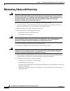
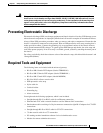
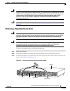
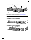
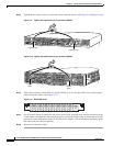
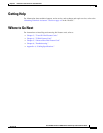
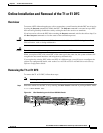
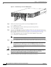
Step 3 Tighten the two captive screws to secure the carrier card to the chassis. (See Figure 2-9 and Figure 2-10.)
Figure 2-9 Tighten the Captive Screws on the Cisco AS5350
Figure 2-10 Tighten the Captive Screws on the Cisco AS5400
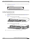
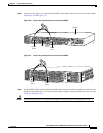
Step 4
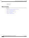
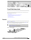
If the carrier card has a blank DFC slot, install a blank cover over the open DFC slot to ensure proper
airflow inside the chassis. (See Figure 2-11.)
Figure 2-11 Blank DFC Cover
Step 5
For AC powered units, reconnect the AC power cord. For DC powered units, remove the tape from the
circuit breaker switch handle, and reinstate power by moving the handle of the circuit breaker to the ON
position. For more information on the AC and DC power supplies, refer to the chassis installation guide
that came with your universal gateway.
Step 6 Reconnect all interface cables.
36005
Captive screw
Captive screw
37162
Captive
screw
Captive
screw
36033