


A-1
Cisco AS5350 and Cisco AS5400 Universal Gateway Card Installation Guide
78-13311-01
APPENDIX
A
Cabling Specifications
This appendix provides cabling and pinout information for dial feature cards (DFCs) on the
Cisco AS5350 and Cisco AS5400 universal gateway:
• T1 and E1 Cable and Port Pinouts, page A-1
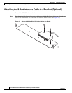
• Attaching the 8-Port Interface Cable to a Bracket (Optional), page A-8
• CT3 Cable and Port Pinouts, page A-13
• Bantam Jack Port Pinouts, page A-13
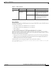
Note This appendix specifies pinouts only for the pins used. Pins not listed in the tables in this appendix
are not connected.
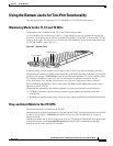
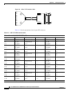
T1 and E1 Cable and Port Pinouts
2-Port and 4-Port T1 or E1 DFC
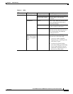
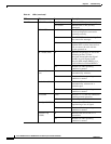
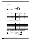
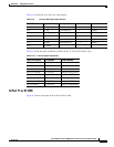
Table A-1 T1 or E1 Port Pinouts
RJ-45 Pin Description
1RX Tip
2RX Ring
3 RX Shield
4TX Tip
5TX Ring
6 TX Shield
7-
8-