


A-12
Cisco AS5350 and Cisco AS5400 Universal Gateway Card Installation Guide
78-13311-01
Appendix A Cabling Specifications
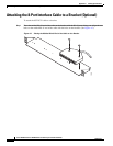
Attaching the 8-Port Interface Cable to a Bracket (Optional)
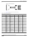
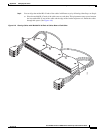
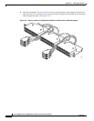
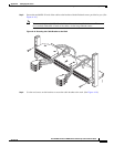
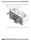
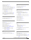
Step 5 Insert the 36-pin cable connector into the 36-pin port on the AS54-DFC-8CT1/CE1 card. Tighten the
captive screws on the 36-pin cable connector to secure the cable to the AS54-DFC-8CT1/CE1 card. (See
Figure A-11.)
Figure A-11 Connecting the 36-Pin Cable Connector to an 8-Port T1 DFC
35062