


3-10
Cisco AS5350 and Cisco AS5400 Universal Gateway Card Installation Guide
78-13311-01
Chapter 3 T1 and E1 Dial Feature Cards
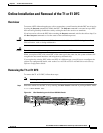
Online Installation and Removal of the T1 or E1 DFC
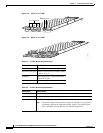
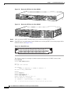
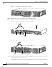
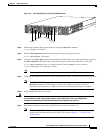
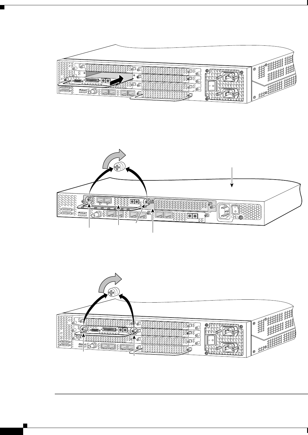
Figure 3-12 Install the T1 or E1 DFC in the Cisco AS5400
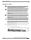
Step 3
Align the captive screws with their holes, and seat the card completely.
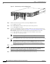
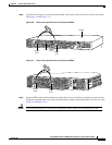
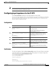
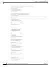
Step 4 Tighten the screws to secure the DFC to the chassis. (See Figure 3-13 and Figure 3-14.)
Figure 3-13 Tighten the Captive Screws on the Cisco AS5350
Figure 3-14 Tighten the Captive Screws on the Cisco AS5400
Step 5
Check the card LEDs to verify that the card is working properly. For information about dial feature card
LEDs, refer to Chapter 6, “Troubleshooting”
37165
36817
0
R
x
A
C
T
2
P
R
I
O
K
T
x
1
Carrier
card
DFC
Captive
screw
Captive
screw
Chassis
37163
Captive
screw
Captive
screw