


4-4
Cisco AS5350 and Cisco AS5400 Universal Gateway Card Installation Guide
78-13311-01
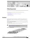
Chapter 4 T3 Dial Feature Card
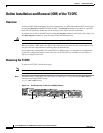
Online Installation and Removal (OIR) of the T3 DFC
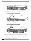
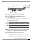
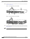
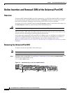
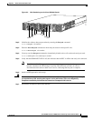
Step 8 Loosen the two captive screws that secure the DFC to the chassis until each screw is free of the chassis.
(See Figure 4-4 and Figure 4-5.)
Figure 4-4 Loosen the Captive Screws on the Cisco AS5350
Figure 4-5 Loosen the Captive Screws on the Cisco AS5400
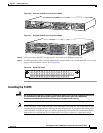
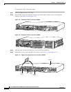
Step 9
Grasp the DFC handle with one hand and pull the card toward you until the card slides free of the chassis.
Grasp the ventilated metal cover with your other hand to support and guide the DFC out of the slot. (See
Figure 4-6 and Figure 4-7.)
Caution Avoid touching any pins or circuit board components during removal and installation of the DFC.
58760
Carrier
card
DFC
Captive
screw
Captive
screw
Chassis
37167
Captive
screw
Captive
screw