


CHAPTER
3-1
Cisco AS5350 and Cisco AS5400 Universal Gateway Card Installation Guide
78-13311-01
3
T1 and E1 Dial Feature Cards
This chapter describes the installation and removal procedures for the T1 and E1 dial feature cards
(DFC) and includes the following sections:
• Overview, page 3-1
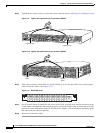
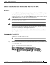
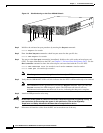
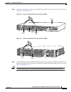
• Online Installation and Removal of the T1 or E1 DFC, page 3-3
• Configuring Input Impedance for the E1 DFC, page 3-11
• Getting Help, page 3-14
• Where to Go Next, page 3-14
Overview
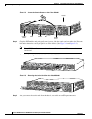
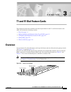
You can install a T1 or E1 dial feature card in any dial feature card slot of the universal gateway chassis.
(See Figure 3-1 through Figure 3-3.)
Each T1 or E1 DFC provides physical line termination for multiple DS-0 channels and uses onboard
HDLC controllers to terminate digital (ISDN) calls. For network specifications see Table 3-1 and
Table 3-2. You can use the bantam ports on the DFC to monitor a line.
Note The Cisco AS5350 and Cisco AS5400 support only one type of WAN DFC at a time. Refer
to Chapter 6, “Troubleshooting” for more information.
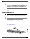
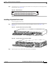
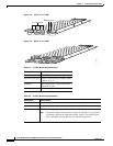
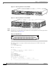
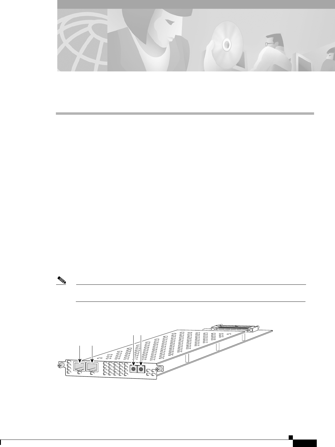
Figure 3-1 2-Port T1 or E1 DFC
35840
T1 or E1 ports
Bantam ports
0
Rx
ACT
2
P
R
I
OK
Tx
1