


6-6
Cisco AS5350 and Cisco AS5400 Universal Gateway Card Installation Guide
78-13311-01
Chapter 6 Troubleshooting
Environment Monitoring
Environment Monitoring
Overview
The Cisco AS5350 and Cisco AS5400 contain temperature sensors to detect abnormal temperature
conditions during system operation. The three levels of sensor detection are as follows:
1. When the operating temperature of the system exceeds 45° C, the system reaches a warning state. A
warning message appears on the console. When the operating temperature of the system drops below
45° C, another message is displayed on the console indicating a recovery. At this level of sensor
detection, there is no disruption in system operation.
2. When the operating temperature of the system continues to rise above 45° C and reaches a
temperature of 60° C, the system reaches a critical state.
Cisco IOS software busys out the DFCs in the chassis and shuts down the first DFC. If the operating
temperature continues to be critical after 10 minutes, Cisco IOS software shuts down another DFC.
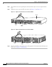
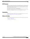
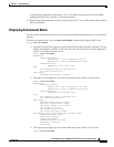
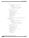
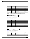
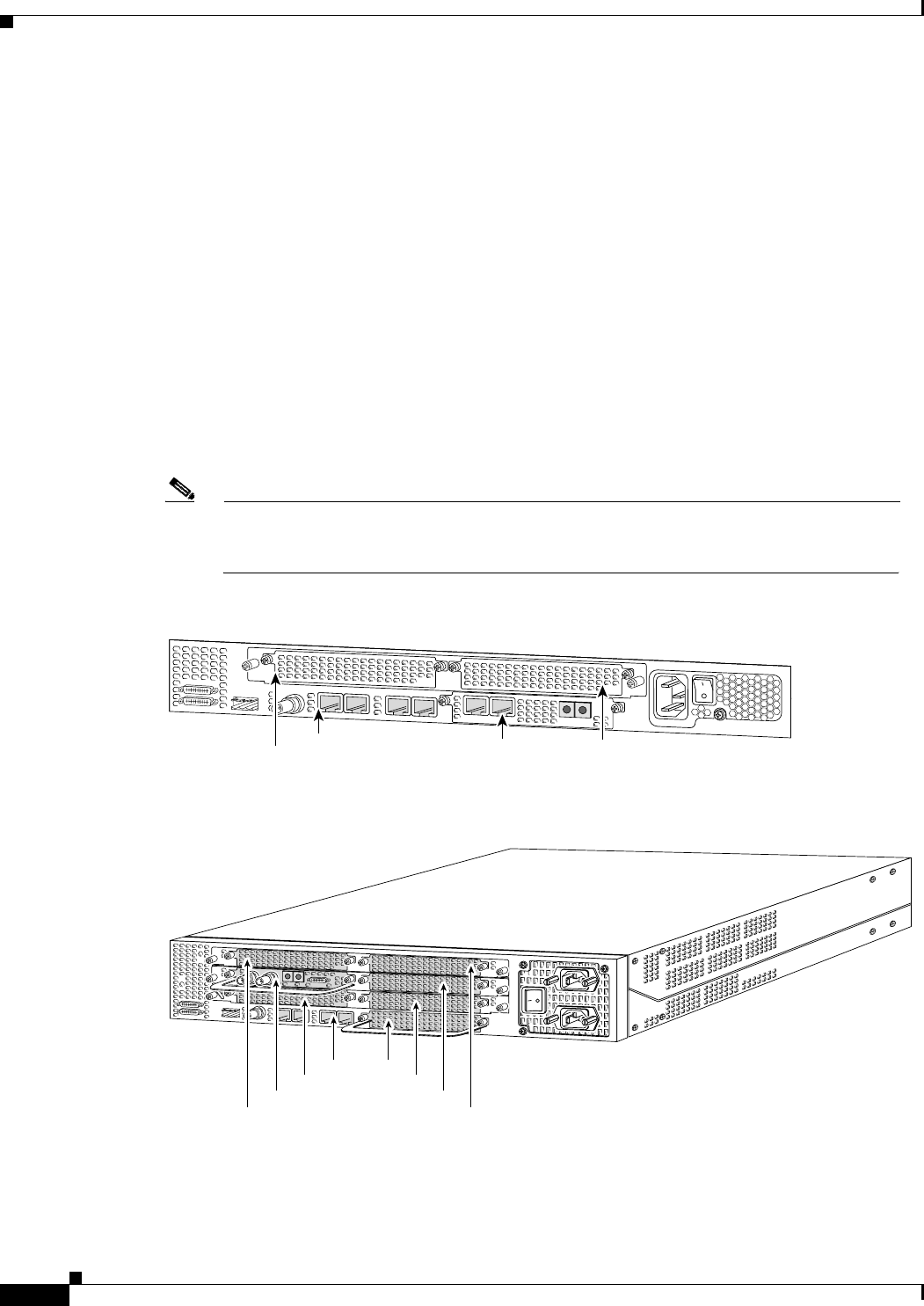
Note DFC slot numbering starts from the system board and works up from left to right. Slot 0 is
reserved for the motherboard. The DFC slots are numbered sequentially. (See Figure 6-5 and
Figure 6-6.)
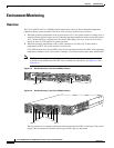
Figure 6-5 Slot Numbering on the Cisco AS5350 Chassis
Figure 6-6 Slot Numbering on the Cisco AS5400 Chassis
The busyout process is repeated at 10 minute intervals until the final DFC is shut down. The console
displays the slot number of the DFC and the type of DFC that was shut down.
36006
Slot 2
Slot 0
Slot 1
Slot 3
34977
Slot 1Slot 0
Slot 2
Slot 4
Slot 6
Slot 3
Slot 5
Slot 7