


Index
IN-2
Cisco AS5350 and Cisco AS5400 Universal Gateway Card Installation Guide
78-13311-01
E
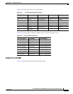
E1 network specifications (table) 3-2
environment monitoring 6-6
environment status, checking 6-7
ESD wrist-strap, safety 1-3
F
Figures
2-Port or 4-Port T1 or E1 DFC LEDs
6-1
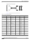
2-Port T1 or E1 DFC 3-1
4-Port T1 or E1 DFC 3-2
8-Port T1/E1 Interface Cable A-3
8-Port T1 or E1 DFC 3-2
8-Port T1 or E1 DFC LEDs 6-2
Bantam Ports 6-9
Blank DFC Cover 2-5, 3-6, 4-5, 5-5
Carrier Card With Two 8 PRI CT1/CE1 Cards 2-2
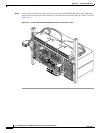
Connecting the 36-Pin Cable Connector to an 8-port T1
DFC
A-9
CT3 Cable Assembly A-10
Install the Carrier Card in the Cisco AS5350 2-5
Install the Carrier Card in the Cisco AS5400 2-5
Install the DFC in the Cisco AS5400 5-7
Install the T1 or E1 DFC in the Cisco AS5350 3-9
Install the T1 or E1 DFC in the Cisco AS5400 3-10
Install the T3 DFC in the Cisco AS5350 4-6
Install the T3 DFC in the Cisco AS5400 4-6
Install the Universal Port DFC in the Cisco AS5350 5-7
J-45 to DB-15 Interface Cable A-2
Loosen the Captive Screws on the Cisco AS5350 2-3,
3-5, 4-4, 5-4
Loosen the Captive Screws on the Cisco AS5400 2-4,
3-5, 4-4, 5-4
Placing the Molded RJ-45 End of the Cable on the
Bracket
A-5
Remove the DFC from the Cisco AS5350 3-6, 4-5, 5-4
Remove the DFC from the Cisco AS5400 3-6, 4-5, 5-5
Removing the Carrier Card from the Cisco AS5350 2-4
Removing the Carrier Card from the Cisco AS5400 2-4
RJ-45 to Bare Wire Interface Cable A-2
RJ-45 to BNC Interface Cable for 75-Ohm, Unbalanced
Connections
A-2
RJ-45 to RJ-45 Interface Cable A-2
RJ-45 to Twinax Interface Cable for 120-Ohm,
Balanced Connections
A-2
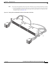
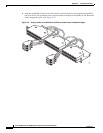
Routing Cables with Molded RJ-45 Ends of Cables
Flush with Bracket Edges
A-7
Routing Cables with Molded RJ-45 Ends of Cables Next
to Each Other
A-6
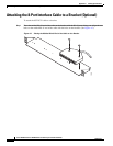
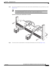
Securing the Cable Bracket to the Rack A-8
Slot Numbering on the Cisco AS5350 Chassis 3-3, 4-2,
5-2, 6-6
Slot Numbering on the Cisco AS5400 Chassis 3-4, 4-3,
5-3, 6-6
T3 DFC LEDs 6-2
T3 Dial Feature Card 4-1
Tighten the Captive Screws on the Cisco AS5350 2-6,
3-10, 4-6, 5-8
Tighten the Captive Screws on the Cisco AS5400 2-6,
3-10, 4-7, 5-8
Universal Port DFC 5-1
Universal Port DFC LEDs 6-2
G
ground connection first warning 1-2
ground connections, safety 1-2
H
hardware features, new xiii
help, getting xii, 2-7, 3-14, 4-7, 5-9, 6-10
I
input impedance, configuring 3-11
input impedance, verifying 3-11
installation instructions warning 1-2
installing a carrier card 2-5