


1-3
Cisco AS5350 and Cisco AS5400 Universal Gateway Card Installation Guide
78-13311-01
Chapter 1 Safety Warnings, Recommendations, and Tools Required
Preventing Electrostatic Discharge
Warning
This product relies on the building’s installation for short-circuit (overcurrent) protection. Ensure
that a fuse or circuit breaker no larger than 120 VAC, 15A U.S. (240 VAC, 10A international) is used
on the phase conductors (all current-carrying conductors). To see translations of the warnings that
appear in this publication, refer to the Regulatory Compliance and Safety Information document
that accompanied this device.
Preventing Electrostatic Discharge
Electrostatic discharge (ESD) can damage equipment and impair electrical circuitry. ESD damage occurs
when electronic components are improperly handled and can result in complete or intermittent failures.
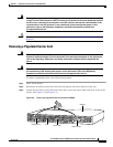
Always follow ESD-prevention procedures when you remove and replace components. Ensure that the
chassis is electrically connected to earth ground. Wear an ESD-preventive wrist strap, ensuring that it
makes good skin contact. Connect the grounding clip to an unpainted surface of the chassis frame to
safely ground unwanted ESD voltages. To guard against ESD damage and shocks, the wrist strap and
cord must operate properly. If no wrist strap is available, ground yourself by touching the metal part of
the chassis.
For safety, periodically check the resistance value of the antistatic strap, which should be between 1 and
10 megohm (Mohm).
Required Tools and Equipment
The following items are included with the universal gateway:
• RJ-45-to-DB-9 female DTE adapter (labeled TERMINAL)
• RJ-45-to-DB-25 female DTE adapter (labeled TERMINAL)
• RJ-45-to-DB-25 male DCE adapter (labeled MODEM)
• RJ-45-to-RJ-45 rollover console cable
• ESD-preventive wrist strap
• Nylon cable tie
• Cable tie holder
• Grounding lug
• Alarm connector
You might need the following equipment, which is not included:
• Straight-through RJ-45-to-RJ-45 cable for an Ethernet connection
• Ethernet hub or PC with a network interface card for Ethernet LAN connections
• One breakout cable consisting of a 36-pin connector connected to eight RJ-45 adaptors for CT1/CE1
connections
• Straight through RJ-45-to-RJ-45 cable for CT1/CE1 connections
• 75-ohm coaxial cable for a CT3 connection
• PC running terminal emulation software for local administrative access
• Modem for remote administrative access