


4-3
Cisco AS5350 and Cisco AS5400 Universal Gateway Card Installation Guide
78-13311-01
Chapter 4 T3 Dial Feature Card
Online Installation and Removal (OIR) of the T3 DFC
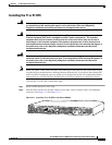
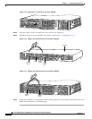
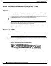
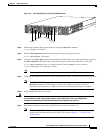
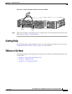
Figure 4-3 Slot Numbering on the Cisco AS5400 Chassis
Step 2
Initialize the software busyout procedure by entering the busyout command:
Router# busyout slot-number
Step 3 Enter the show busyout command to check busyout status for that specific slot:
Router# show busyout slot-number
Step 4 You may use the clear port command to immediately disable active calls on the universal port card. Use
the show controller command to show the universal port card associated with the T1 or E1 DFC.
Router# show controller t1/e1 slot-number/control-number timeslot timeslot-number
Router# clear port slot-number/port number
Note The clear port command only applies to the universal port DFC.
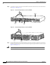
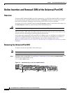
Step 5 Verify that the OIR/MAINT LED is off; this indicates that the DFC is offline and ready to be removed.
Note The OK/MAINT LED is green before you enter the busyout command. After you enter the
busyout command, the LED changes to yellow. The LED turns off after all calls are
disconnected and resources are taken out of service, indicating that busyout is complete.
Step 6 Attach an ESD-preventive wrist strap.
Warning
Do not work on the system or connect or disconnect cables during periods of lightning activity. To
see translations of the warnings that appear in this publication, refer to the Regulatory
Compliance and Safety Information document that accompanied this device.
Step 7 Disconnect all interface cables from the DFC and secure them out of the way.
Note OIR of the T3 DFC is similar to that of the T1 or E1 DFC. To see an example of the output
during online insertion and removal of an E1 DFC refer to Chapter 3, “T1 and E1 Dial
Feature Cards”
34977
Slot 1Slot 0
Slot 2
Slot 4
Slot 6
Slot 3
Slot 5
Slot 7