


7 - 18
– +
ELEC
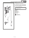
CHARGING SYSTEM
EBS01066
NO
YES
EBS01100
YES
NO
EBS01059
YES
NO
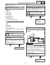
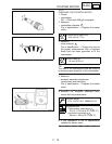
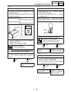
3. Charging voltage
• Connect the engine tachometer to the
spark plug lead.
• Connect the pocket tester (DC 20 V) to the
battery as shown.
Positive tester probe →
positive battery terminal
Negative tester probe →
negative battery terminal
• Start the engine and let it run at approxi-
mately 5,000 r/min.
• Measure the charging voltage.
Charging voltage
14 V at 5,000 r/min
TIP
_
Make sure the battery is fully charged.
• Is the charging voltage within specifica-
tion?
The charging circuit
is OK.
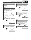
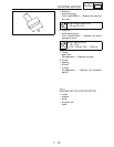
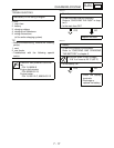
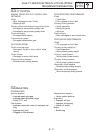
4. Charging coil resistance
• Disconnect the C.D.I. magneto coupler
from the wire harness.
• Connect the pocket tester (
Ω ×
1) to the
charging coils.
Positive tester probe → white terminal
Negative tester probe → white terminal
• Measure the charging coil resistance.
Charging coil resistance
0.60 ~ 0.90 Ω at 20 °C (68 °F)
(between white and white)
Replace the rectifier/
regulator.
Replace the pickup
coil/stator assembly.
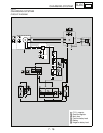
5. Wiring
• Check the entire charging system’s wiring.
Refer to “CIRCUIT DIAGRAM”.
• Is the charging system’s wiring properly
connected and without defects?
The charging system
circuit is OK.
Properly connect or
repair the charging
system’s wiring.
DC20V
W
W
W/B
W/R
1
2
2