


24-Pump, 128-Station Controller Chapter 3: Installation 24
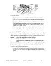
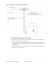
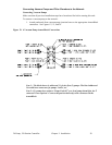
1. Attach a KwikLink connector included in the bag with power cables to the flat
cables. One connector is used for the network grey cable and one connector is used
for the auxiliary power black cable.
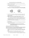
2. Align the square connector of the grey drop cable so the cable leads down from the
connector. Evenly press the square connector onto the top of the bottom KwikLink
connector. It should make two audible snaps when properly seated.
3. Align the square connector of the black drop cable so the cable leads down from the
connector. Evenly press the square connector onto the top of the upper KwikLink
connector. It should make two separate, audible snaps when properly seated.
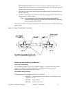
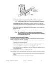
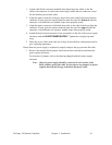
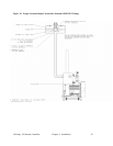
4. Attach the keyed round connectors to the receptacles on the side of the power supply
enclosure marked 24 VDC POWER SUPPLY. Tighten the cord grip ring until
snug.
5. Dress the excess cables with cable ties so they do not interfere with operation and to
give a pleasing appearance.
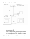
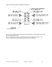
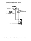
If more than one power supply is required to properly energize the grey network flat cable:
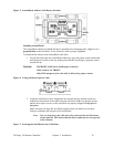
1. Remove the terminal block jumpers on all but the most centrally-located network
power supply enclosures.
For locations of jumpers, refer to the drawing shipped inside the power supply
enclosure
Note: Only one power supply should be connected to each section of the
black auxiliary power flat cable. Do not remove any jumpers on power
supplies that transmit energy to the black flat power cable.