


24-Pump, 128-Station Controller Chapter 3: Installation 15
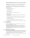
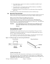
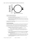
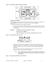
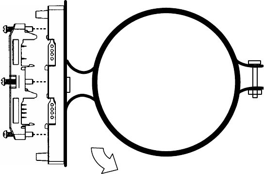
Figure 3: Side View of a Typical Mounting Plate Assembly with ArmorBlock Base
Rotate 30º to 45º downward
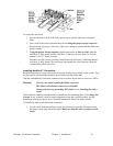
Installing Assembled Mounting Plates
After you’ve set up the mounting plates:
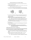
1. Install them at each node location by clipping the tubing clamps onto the vacuum
tube, just before the node area (such as a T-valve).
2. Orient the mounting plate parallel with the flat cables and at a 30º to 45º angle so the
KwikLink connector or ArmorBlock faces the operator on the floor; torque the tubing
clamp fasteners until tight.
The flat cable will be installed inside KwikLink connectors and ArmorBlocks as described in
the following sections of this chapter.
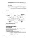
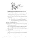
Terminating Cable Runs
After you’ve run the black and grey network cables, you need to properly terminate the ends
of the cables. By doing so, you’ll insure that the network runs properly. You will also have
the benefit of being able to measure voltage in the system without disrupting operation.
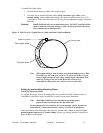
This section lists procedures for terminating these cables. To properly terminate a cable run:
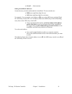
1. Mount three standard KwikLink connectors to a mounting plate in a triangle
configuration. See Figure 4 on Page 19 for an illustration.
Make sure that each connector is installed with the hinge side down.
2. Mount the tubing clamps to the mounting plates. Each mounting plate requires two
(2) tubing clamps.
3. Mount the standard resistor cap from the KwikLink connector kit on the top center
KwikLink connector for the black power flat cable. The standard resistor cap has
metal prongs in the center.
Repeat for the outside end KwikLink connector on the grey data flat cable.
4. For the inside KwikLink connector (next to the outside end on the grey cable), mount
a separately-packaged blank cap on it instead of the standard resistor cap in the
KwikLink connector kit.