


24-Pump, 128-Station Controller Chapter 3: Installation 22
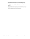
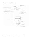
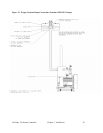
3. Run the cables from the remote interface(s) to the switch and the main controller,
neatly dressing the cable with ties so that it does not interfere with system operation
and it gives a neat appearance.
4. Attach RJ45 connectors at each cable end following the connector manufacturers
instructions.
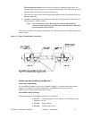
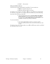
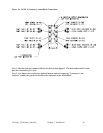
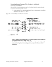
5. The “Ethernet out” connection on the main controller should connect to the “Ethernet
in” connection on the switch.
6. The “Ethernet out” connections on the switch should connect to the “Ethernet in”
connections on the main controller and the remote interface(s).