


24-Pump, 128-Station Controller Chapter 3: Installation 21
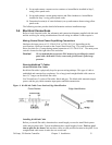
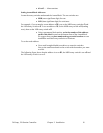
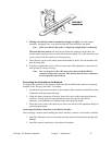
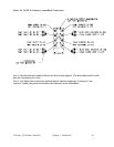
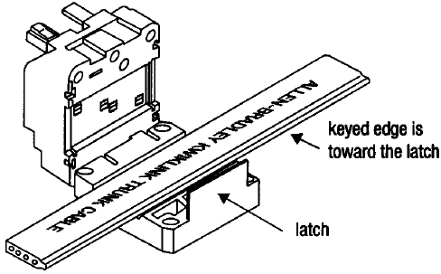
2. Making sure that the cable is completely straight, carefully close the hinged
assembly, and apply firm, even pressure until the first latch locks into place.
Note: Make sure that the flat cable is completely straight before continuing!
The latch has two catches; the first loosely holds the connector on the cable, the
second requires more pressure to close the connector tightly. The cable must be in the
correct position for the connector to close properly.
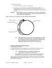
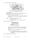
3. Drive the two screws at the center points about halfway down; first on the latch side,
then the hinge side.
4. Continue to tighten the screws a little at a time until fully tightened; no more than 15
inch-pounds (5.6 N
•m) of torque.
Note: You can only pierce the cable once. Once pierced, the KwikLink
connector must not be removed. This insures that the inner conductors
are not exposed to the elements.
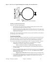
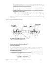
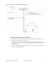
Connecting the Controller to the Network
To connect the controller to the network, make sure that the KwikLink connector is properly
installed on the flat grey data cable. To connect:
1. Attach the keyed round connector to the terminal of the controller marked DeviceNet.
Tighten the cord grip ring until snug.
2. Align the square connector of the grey drop cable so the cable leads down from the
connector. Evenly press the square connector onto the top of the KwikLink
connector. It should make two audible snaps when properly seated.
3. Dress the excess cable with cable ties so it does not interfere with operation and gives
a pleasing appearance.
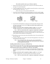
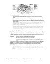
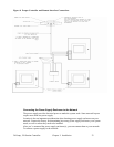
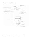
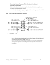
Connecting the Remote Interface to the Main Controller
After selecting a location and installing the remote interface, connect it to the main controller:
1. Install the Ethernet switch in a location safe from electrical interference and physical
damage.
2. Install the remote interface(s) in their desired locations.