


24-Pump, 128-Station Controller Chapter 3: Installation 16
Discard the standard resistor cap to eliminate confusion.
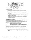
5. Mount the mounting plate assembly on the vacuum line at the end of the cable run.
See Page 14 for more information.
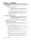
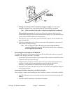
6. Using the straight-blade cable cutter, carefully trim each flat cable so it sticks out past
the final KwikLink connector by
1
/4” to
3
/8”.
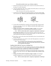
Place a dust cap over the end of the trimmed cable.
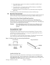
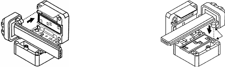
7. Lay the dust cap and cable into the KwikLink connector so the dust cap tabs engage
in the connector slots. The dust cap tabs should fit into the connector slots perfectly.
Left Right
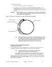
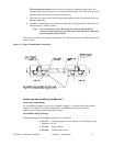
8. Lay the cable in the hinged base, noting the correct keyed profile; flat edge toward
the hinge, keyed edge toward the latch. Make sure that the cable and dust cap are
properly seated inside.
9. Making sure that the cable is completely straight, carefully close the hinged
assembly, and apply firm, even pressure until the first latch locks into place.
Note: Make sure that the flat cable is completely straight before continuing!!
The latch has two catches; the first loosely holds the connector on the cable, the
second requires more pressure to close the connector tightly. The cable must be in the
correct position for the connector to close properly.
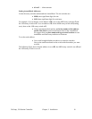
10. Drive the two screws at the center points about halfway down; first on the latch side,
then the hinge side.
11. Continue to tighten the screws a little at a time until fully tightened; no more than 15
inch-pounds (5.6 N
•m) of torque.
Note: You can only pierce the cable once. Once pierced, the KwikLock
connector must not be removed. This insures that the inner conductors
are not exposed to the elements.
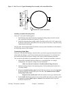
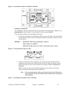
Installing Inside KwikLink Connectors with Blank Caps
Once installed on the grey data cables, these connectors permit you to measure voltage in the
system so you can analyze how it is working. The system cannot work properly unless these
inside-mounted connectors have the blank (non-conductor) caps installed.
1. Lay the cable in the hinged base, noting the correct keyed profile; flat edge toward
the hinge, keyed edge toward the latch. Make sure that the cable is properly seated
inside.
2. Making sure that the cable is completely straight, carefully close the hinged
assembly, and apply firm, even pressure until the first latch locks into place.
Note: Make sure that the flat cable is completely straight before continuing!!