Section 34 User Debugging Interface
Page 1824 of 2108 R01UH0134EJ0400 Rev. 4.00
Sep 24, 2014
SH7262 Group, SH7264 Group
34.4 Operation
34.4.1 TAP Controller
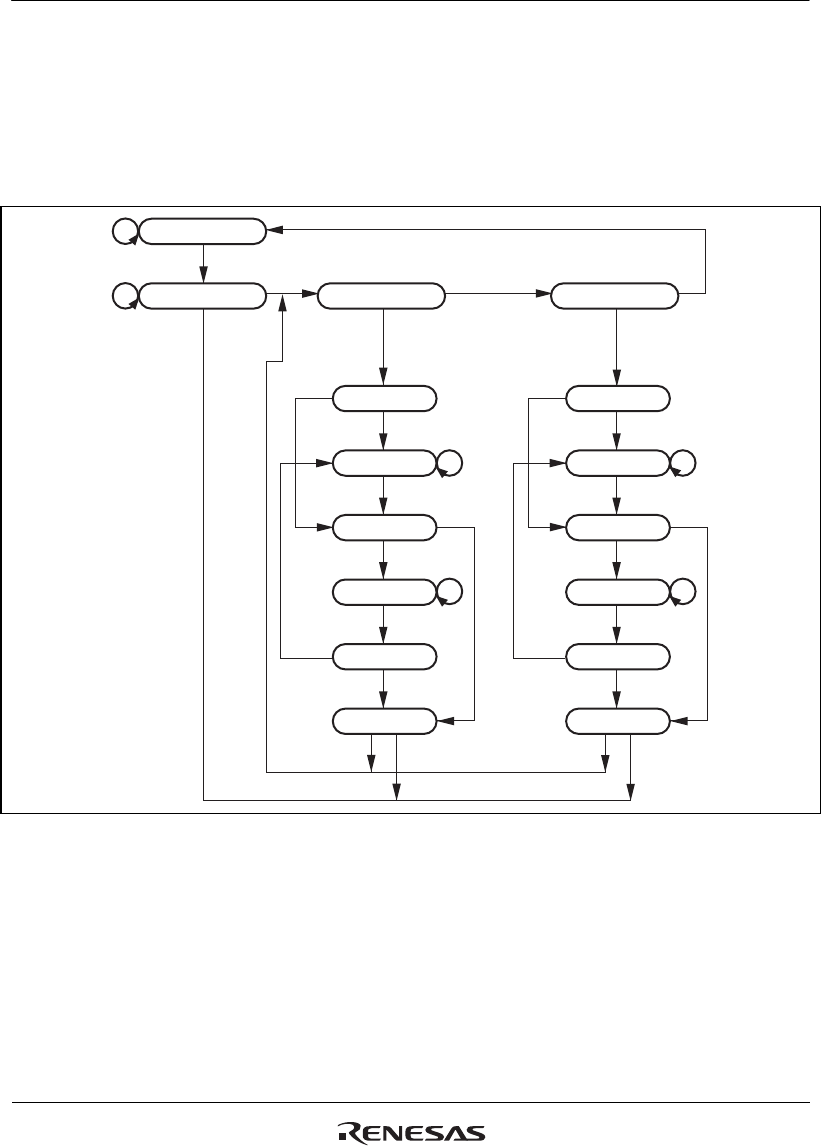
Figure 34.2 shows the internal states of the TAP controller. This state machine conforms to the
state transitions defined by JTAG.
Test -logic-reset
Capture-DR
Shift-DR
Exit1-DR
Pause-DR
Exit2-DR
Update-DR
Select-DRRun-test/idle
1
0
0
0
0
11 1
1
0
0
0
1
11
0
1
1
1
0
Capture-IR
Shift-IR
Exit1-IR
Pause-IR
Exit2-IR
Update-IR
Select-IR
0
0
1
0
0
0
1
0
1
1
10
Figure 34.2 TAP Controller State Transitions
Note: The transition condition is the TMS value at the rising edge of TCK. The TDI value is
sampled at the rising edge of TCK; shifting occurs at the falling edge of TCK. For details
on transition timing of the TDO value, see section 34.4.3, TDO Output Timing. The TDO
is at high impedance, except with shift-DR and shift-IR states. During the change to TRST
= 0, there is a transition to test-logic-reset asynchronously with TCK.


