


8 PARAMETER FUNCTIONS
8-16
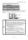
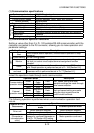
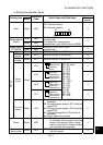
(5) Explanation of communication data structure
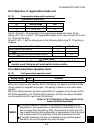
1) Control codes
The following table lists the ASCII codes and their definitions of the control
code names which are set at the beginning, end and like of the format.
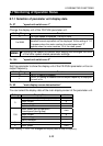
Signal Name ASCII Code Description
STX H02 Start of Text (Start of data)
ETX H03 End of Text (End of data)
ENQ H05 Enquiry (Communication request)
ACK H06 Acknowledge (No data error detected)
LF H0A Line Feed
CR H0D Carriage Return
NAK H15 Negative Acknowledge (Data error detected)
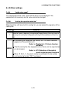
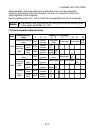
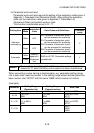
2) Station number
Specify the station number of the drive unit used for communication with the
computer.
Specify the drive unit station number within the range H00 to H1F (stations
0 to 31) in hexadecimal.
The communication data is converted into ASCII automatically.
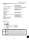
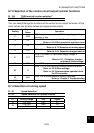
Example: H00 (binary)
H3030 (ASCII)
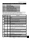
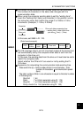
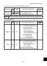
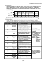
3) Instruction codes and data codes
The instruction code and data code have been set in correspondence with
the operation mode, operation or parameter write or read.
The communication data is converted into ASCII automatically.
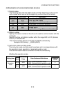
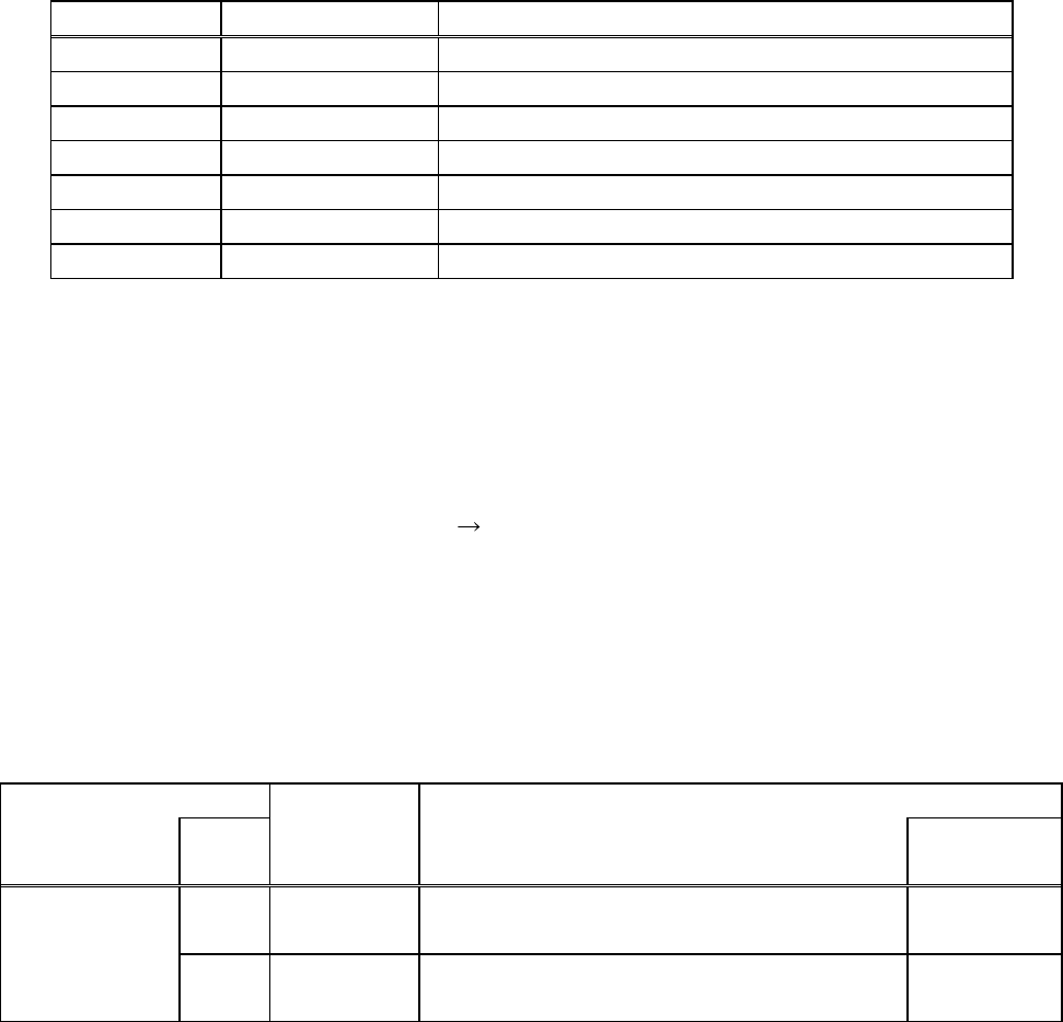
i) Setting the operation mode
Setting Item
Mode
Instruction
Code
Data Codes and Definitions
Character
count
Write HFB
H0001: External operation mode
H0002: Communication operation mode
4
Operation
mode
Read H7B
H0001: External operation mode
H0002: Communication operation mode
4