


2. INSTALLATION
2-2
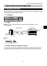
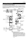
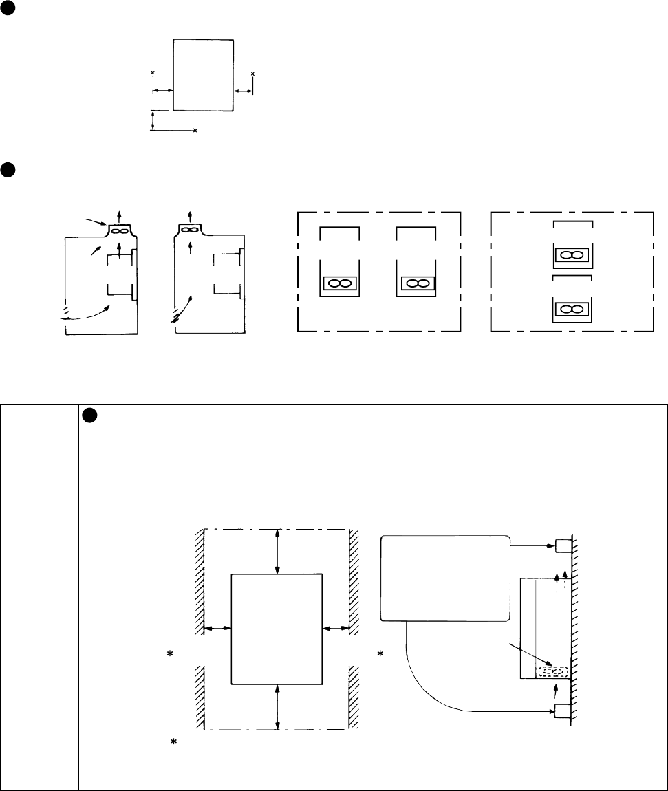
2.1.2 Installation in control box
When installing the drive unit in a control box, the internal temperature of the
control box must not exceed the permissible value due to drive-unit generated
heat and peripheral-generated heat.
Placing a heat sink outside the control box can reduce the heat generated inside
the control box.
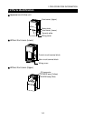
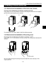
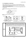
Measurement positions of ambient temperatures
5cm 5cm
5cm
Measurement position
Drive
unit
Measurement position
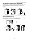
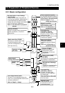
Layout of drive units within control box
V
entilation fan
Drive unit
(Correct example) (Incorrect example)
Drive unit
Position of ventilation fan
Built-in cooling fans
Accommodation of two or more drive units
Drive unit Drive unit
Drive unit
Drive unit
(Incorrect example)(Correct example)
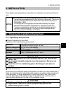
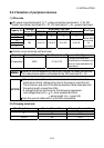
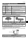
NOTICE
Leave the specified clearances between the drive unit and control
box walls or other equipment. Not doing so can cause a failure. In
addition, improper convection of air in the control box will reduce the
heat dissipation effect. Fully consider the equipment layout in the
control box and the use of a cooling fan for ventilation, for example.
10cm
or more
1cm
or more
Drive unit
1cm
or more
These clearances are also required for
re
p
lacement of the coolin
g
fan.
Leave sufficient
clearances above
and under the drive
unit to ensure
adequate ventilation.
Cooling fan built
in the drive unit
Cooling
air
10cm
or more