


3. WIRING
3-9
3
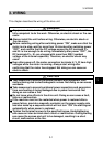
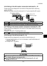
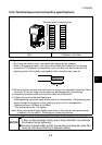
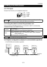
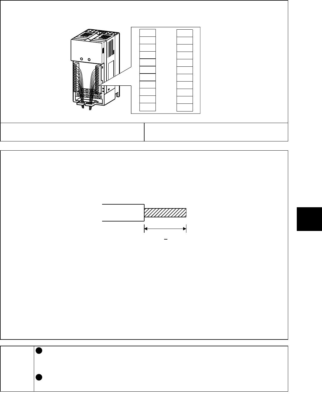
3.3.2 Terminal layout and connection specifications
Layout
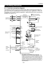
Terminal layout of control circuit
RH
RM
RL
MRS
RES
SD
FM
PC
SE
RUN
FU
A
B
C
10
2
5
4
SD
STF
STR
SD
Screw size
M2.5
Tightening torque
0.25N
•
m to 0.49 N
•
m
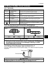
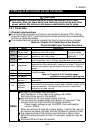
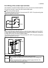
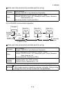
Wiring method
1) For wiring the control circuit, use cables after stripping their sheaths.
Refer to the gauge printed on the drive unit and strip the sheaths to the following
dimensions. If the sheath is stripped too much, its cable may be shorted with the
adjoining cable. If the sheath is stripped too little, the cable may come off.
7mm 1mm
+
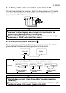
2) When using bar terminals and solid wires for wiring, their diameters should be 0.9mm
maximum. If they are larger, the threads may be damaged during tightening.
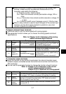
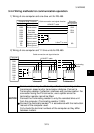
3) Loosen the terminal screw and insert the cable into the terminal.
4) Tighten the screw to the specified torque.
Undertightening can cause cable disconnection or misoperation. Overtightening can
cause damage to the screw or unit, leading to short circuit or misoperation.
Tightening torque: 0.25N
•
m to 0.49N
•
m
* Use a screwdriver No. 0 to tighten.
Note: When routing the stripped cables, twist them so that they do not become loose.
In addition, do not solder it. Soldering can cause poor contact.
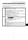
NOTICE
When using a bar terminal or a solid wire for wiring, use one of
0.9mm or less diameter. Using one of larger diameter may damage
the threads during tightening.
Connect stripped cable so that its core does not become loose. Not
doing so can cause shorting of adjacent cables.