


3. WIRING
3-8
MEMO
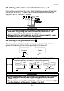
Ratings of transistor output terminals
Max. permissible voltage: 27VDC, max. permissible current:
0.1ADC
NOTICE
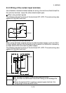
When driving a coil load, connect a diode.
Refer to: 3.3.5 Wiring of the transistor output
terminals
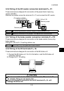
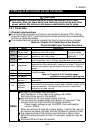
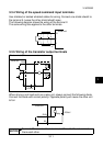
(4) Contact output terminals
When the protective function is activated, the relay contact connected to the
terminal opens/closes.
Refer to: Chapter 6, 6.1.1 Protective function
activated
Symbol Contact Capacity Description
A, B, C
200VAC 0.3A or
30VDC 0.3A
Normal : Terminals B-C closed
(Terminals A-C open)
Protective function activated: Terminals B-C open
(Terminals A-C closed)
MEMO
The response time of the contact output terminals is less than
100ms. (After drive unit output shutoff)
When the drive unit is powered off, the contact output is placed in a
normal status. Therefore, the contact output signal is not held when
power is switched off after the protective function has been
activated. When the signal must be held, provide an external
holding circuit.
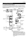
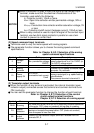
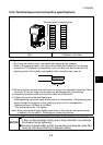
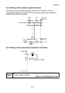
(5) Instrument connection terminals
Used to display the motor speed externally.
You can use the parameter function to choose the item other than the motor
speed.
Refer to: Chapter 8, 8.7.5 Selection of the instrument
connection terminal functions
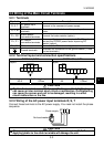
Symbol Name Description
FM
Meter
connection
The output voltage has an 8VDC pulse waveform.
The output varies in proportion to the motor speed and the average
voltage is preset to approx. 4.7V at the rated speed and 1440
pulses/s.
As a meter, use a 1mA moving-coil type DC ammeter or digital
counter.
As the common terminal, use terminal SD.
MEMO
The output signal from the FM terminal is updated at intervals of
several 10ms.