


7. SPECIFICATIONS
7-1
7
7. SPECIFICATIONS
7.1 Standard Specifications
7.1.1 Rating specifications
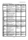
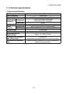
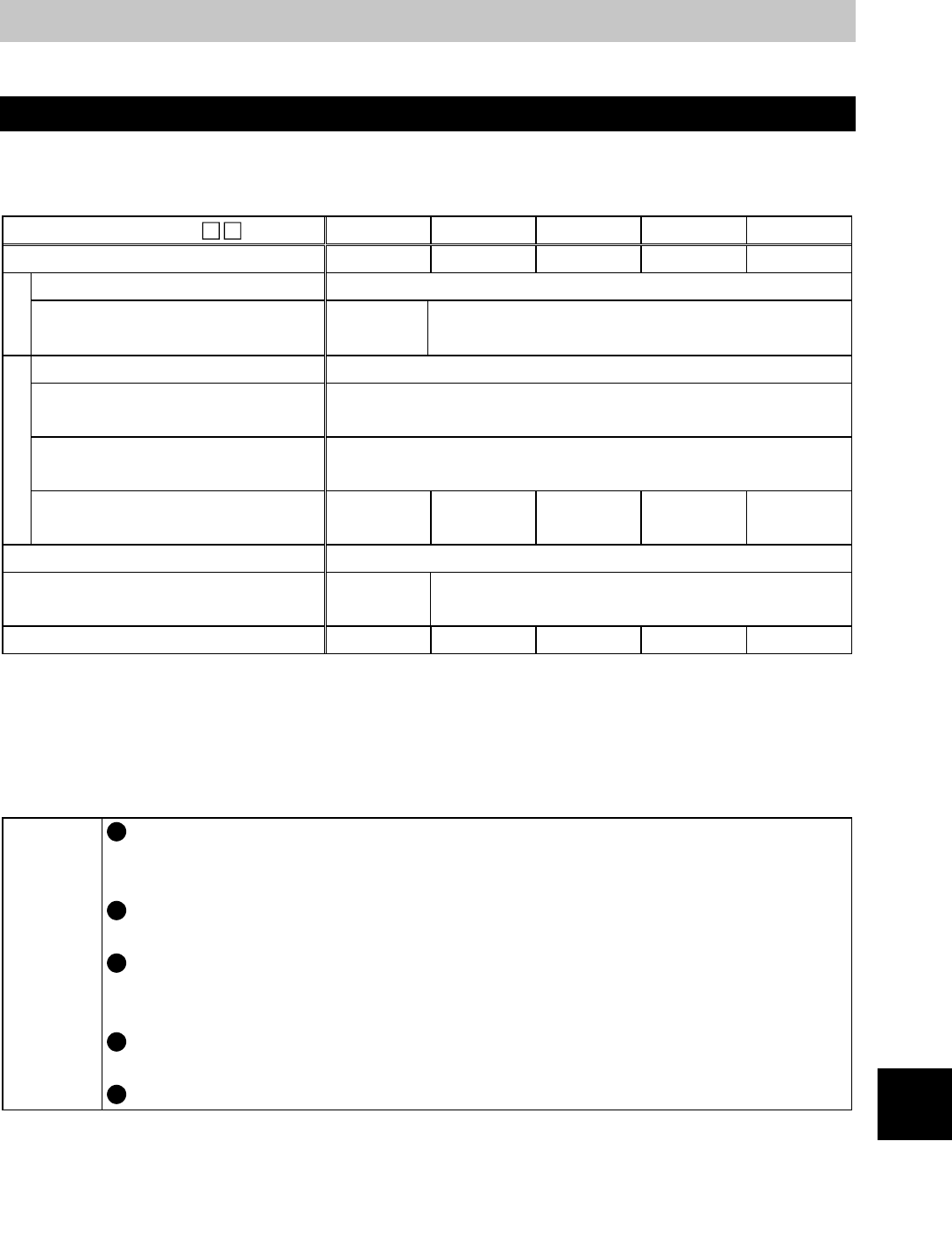
MD-CX522- 0.4K 0.75K 1.5K 2.2K 3.7K
Applicable motor capacity (kW) 0.4 0.75 1.5 2.2 3.7
Overload capacity 150% 60s (inverse-time characteristics)
Output
Regenerative braking torque
(Note 1)
10% or
more
5% or more
Rated input AC voltage Three phase, 200V to 220V 50Hz, 200 to 230V 60Hz
Permissible AC voltage
fluctuation
170 to 242V 50Hz, 170 to 253V 60Hz
Permissible frequency
fluctuation
±
5%
Power supply
Power supply system capacity
(kVA)
1.1 2.2 3.1 4.3 7.3
Protective structure Enclosed type (IP20)
Cooling system
Self-
cooling
Air cooling
Approx. weight (kg) 8.0 1.0 1.7 1.7 2.2
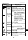
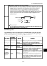
Note 1: Indicates the short-duration average torque (which varies with motor loss) provided
when a motor alone is decelerated from the rated speed at the shortest time, and
does not indicate continuous regenerative torque. Since the drive unit does not
have a built-in brake resistor, use an optional brake resistor when regenerative
energy is large. You can also use the brake unit (model BU).
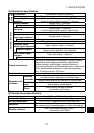
MEMO
The rated output capacity and rated speed of the motor used with
the drive unit assume the rated input AC voltage indicated above.
They cannot be guaranteed when the power supply voltage drops.
The overload capacity indicated in % is the ratio of the overload
current to the motor's rated output.
The power supply system capacity varies with the values of the
power supply side impedances (including those of the input reactor
and cables).
The permissible load inertia moment ratio to the motor shaft is 15
times or less.
The drive unit cannot run multiple motors.