


3. WIRING
3-2
3.1 Pre-Wiring Instructions
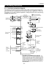
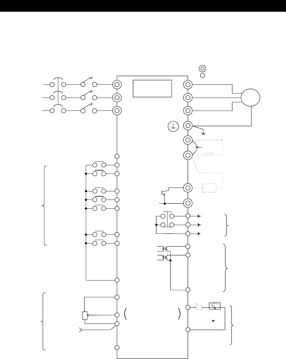
3.1.1 Terminal connection diagram
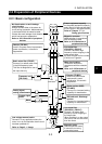
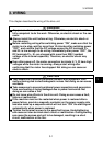
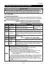
The following shows the wiring of all terminals. After confirming the function of
each terminal, wire necessary terminals according to your application. When the
Parameter unit is used to perform operation, merely doing the main circuit wiring
enables the motor to run.
NFB
R
+
-
R
S
T
U
V
W
PC
STF
STR
RH
RM
RL
MRS
RES
SD
10(+5V)
2
4
(Keep this terminal open)
P1
PR
A
B
C
RUN
FU
SE
FM
SD
P/+
N/-
3-phase AC
power supply
Drive unit
PU connector
(RS-485)
External transistor common
rotation start
rotation start
Forward
Reverse
Low speed
High speed
Middle speed
Contact input
terminals
Output stop
Reset
Speed
command
input
terminals
Speed setting
potentiometer
Common
Voltage
input
Contact
input
common
DC0 to 10V
DC0 to 5V
Switched
5(Analog common)
Meter
connection
terminals
Calibration
resistor
Transistor
output
terminals
Running
Up to speed
Contact output
terminals
Brake resistor
FR-ABR (option)
Power factor improving reactor
FR-BEL (option)
Ground
Jumper
Motor
Control circuit terminal
Main circuit terminal
Transistor
output common
Pulse output
(0 to 1440
pulses/s)
*This resistor is not needed when you use the
parameter unit (FR-PU04) to make calibration. This
resistor is used when you need to calibrate the meter
nearby because the meter is at a remote location, for
example. Note that when you connect the calibration
resistor, the meter may not deflect to the full scale. In
this case, use the parameter unit with the resistor to
make calibration.