MA490
1
6
9
5
1
6
9
5
LINK
ACT
NET
CRAFT
DATA
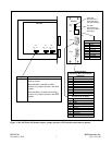
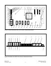
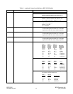
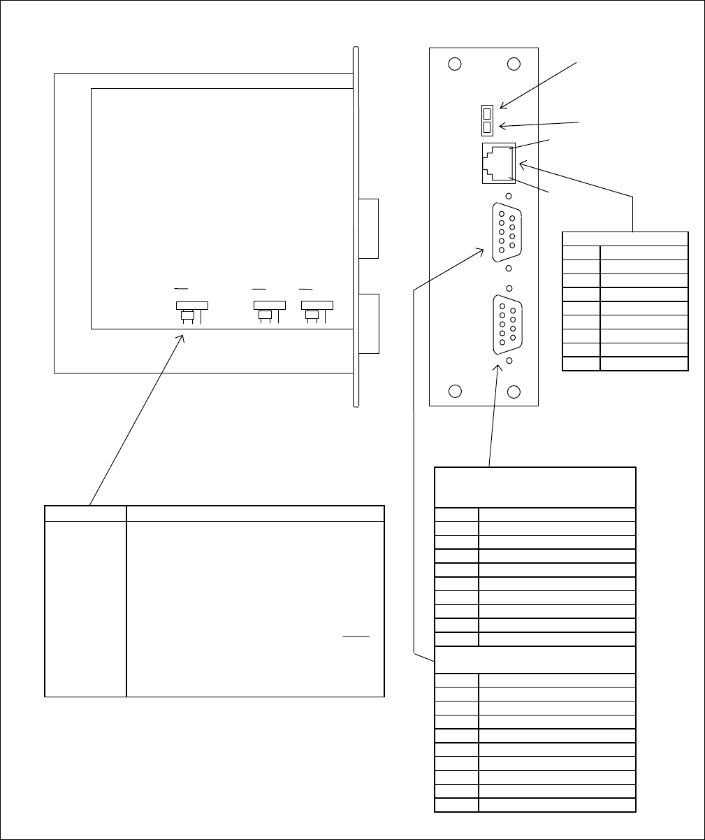
Jumper Function
J1, J2 & J3 Selects NCM Module Mode or Stand Alone
Mode as follows:
When MA-490 is used with an NCM
module, all 3 jumpers must be in the NCM
position.
When MA-490 is not used with an NCM
module, all 3 jumpers must be in the NCM
position.
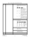
LINK LED
(Ethernet Link is
connected when
LED is illuminated)
ACT LED
(Ethernet Data is
active when LED is
illuminated)
RJ-45 Ethernet Port
Pin Signal
1 E_Tx+
2 E_Tx-
3 E_Rx+
4 not used
5 not used
6 E_Rx-
7 not used
8 not used
1
8
NCM NCM NCM NCM NCM NCM
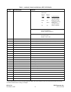
DATA connector
(Connect to CM or other external
equipment)
Pin Signal
1 not used
2 TXD
3 RXD
4 not used
5 ground
6 not used
7 not used
8 not used
9 not used
CRAFT connector
(Connect to PC or laptop)
Pin Signal
1 not used
2 TXD
3 RXD
4 not used
5 ground
6 not used
7 not used
8 not used
9 not used
MA-490
J3 J1 J2
Figure 3. MA-490 Telnet I/O Module adapter, jumper functions, LED functions and connector pinouts
RFL NCM RFL Electronics Inc.
November 6, 2007 7 (973) 334-3100


