


RFL NCM RFL Electronics Inc.
November 6, 2007 40 (973) 334-3100
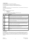
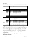
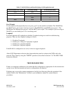
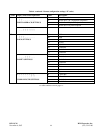
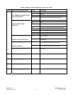
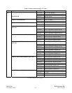
Table 5. Valid NCM Parity and Data Bit Settings in NMS application mode
Common Module Parity Setting NCM Parity Setting NCM Data Bits Setting
Even Even 7
Odd Odd 7
Space Space 7
None 8
Mark Mark 7
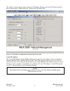
Port 2 Enable
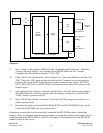
For the interfaces that physically have two ports, port 2 can be enabled or disabled. The MA402I has
two RS232 ports, one on port 1 and one on port 2. The MA490 has one RS485 port on port 1. The
MA490 has one Ethernet port on port 1 and one RS232 port on port 2. For example if you are using an
MA402I, you can disable port 2 if it is not being used.
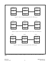
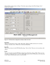
Loopback
In normal operation all loopbacks are disabled. Loopback settings are used for troubleshooting
purposes. There are four loopback settings as follows:
1. Disable all loopbacks
2. Enable port 1 and port 2 equipment loopback
3. Enable port 1 payload loopback
4. Enable port 2 payload loopback
If the MA485 is configured as two wire, it does not support loopback.
After all NCM parameter selections have been made they must be written to the NCM card in the
network. This is done by using the “WRITE” operation as described in Section 7 of The IMUX 2000
Instruction Manual.
TROUBLESHOOTING
If there is an apparent malfunction, first check that the configuration is appropriate for the transmission
system in use, and that transmit and receive configurations are identical.
Problems may occur at the common equipment or facility level that may affect the operation of this
module. Refer to the “Maintenance” section in your multiplexer manual for system analysis
procedures.