


RFL NCM RFL Electronics Inc.
November 6, 2007 16 (973) 334-3100
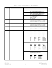
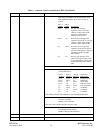
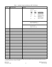
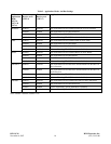
Table 2. Application Modes And Bus Settings
NMS
Application
Mode
(SW7-4,
SW7-5 &
SW7-6)
Transmit on A
Receive on B
(SW2-6)
Transmit on B
Receive on A
(SW2-7)
Application
Broadcast enabled disabled The NCM mode will be Terminal broadcast or DI-A broadcast
disabled enabled The NCM mode will be DI-B broadcast
enabled enabled The NCM mode will be D&I broadcast
disabled disabled (Not a valid setting. The NCM module is disabled)
NMS enabled disabled The NCM mode will be Terminal NMS or DI-A NMS
disabled enabled The NCM mode will be DI-B NMS
enabled enabled The NCM mode will be D&I NMS
disabled disabled (Not a valid setting. The NCM module is disabled)
Master enabled disabled The NCM mode will be Terminal Master or DI-A Master
disabled enabled The NCM mode will be DI-B Master
enabled enabled The NCM mode will be D&I Master
disabled disabled (Not a valid setting. The NCM module is disabled)
D&I Slave enabled disabled The NCM mode will be D&I Slave and the Master NCM node is in
the A direction.
disabled enabled The NCM mode will be D&I Slave and the Master NCM node is in
the B direction.
enabled enabled (Not a valid setting. The NCM module is disabled)
disabled disabled (Not a valid setting. The NCM module is disabled)
D&I End enabled disabled The NCM mode will be Terminal End Slave or DI-A End Slave
disabled enabled The NCM mode will be DI-B End Slave
enabled enabled (Not a valid setting. The NCM module is disabled)
disabled disabled (Not a valid setting. The NCM module is disabled)
Note: enabled = DOWN, disabled = UP