RFL NCM RFL Electronics Inc.
November 6, 2007 14 (973) 334-3100
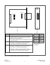
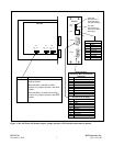
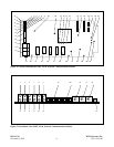
Table 1. - continued, Controls and indicators, RFL NCM Module
Item Name/Description Function
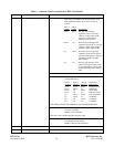
20 DIP Switch, SW7 SW7-1 to SW7-2 Selects CM address pass setting in NMS application
mode only in accordance with the table below. In all
other application modes, these switch settings are
ignored.
SW7-1 SW7-2
(ADR1)
(ADR0) Pass Setting
Down Down Will pass any messages
regardless of the “Local CM
Address” setting of the NCM.
Messages without address
headers are also passed.
Down Up Will only pass messages with
addresses equal to the “Local CM
Address” setting of the
NCM as
defined by SW3, SW4 & SW5.
Up Down Will only pass messages with
addresses greater than or equal to
the “Local CM Address” setting of
the NCM as defined by SW3,
SW4 & SW5.
Up Up Will only pass messages with
addresses less than or equal to the
“Local CM Address” setting of the
NCM as defined by SW3, SW4 &
SW5.
SW7-3 Not Used
SW7-4 to SW7-6 Selects “Application Mode Setting” in accordance
with the table below:
SW7-4 SW7-5 SW7-6 Application
(Mode 2) (Mode 1) (Mode 0) Mode Setting
Down Down Down broadcast mode
Down Down Up NMS mode
Down Up Down master mode
Down Up Up D&I slave mode
Up Down Down End, slave mode
Up Down Up Undefined
Up Up Down Undefined
Up Up Up Undefined
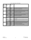
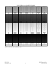
Note: Refer to Table 2 for additional switch setting information.
SW7-7 Enables or disables Port 2
UP = Port 2 enabled
DOWN = Port 2 disabled
Note: Port 2 not available when MA-485 I/O is used.
SW7-8 Enables or disables Rogue Control
UP = Rogue Control enabled
DOWN = Rogue Control disabled
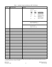
21 DIP Switch, SW8 SW8-1 to SW8-8 Not Used
22 DIP Switch, SW9 SW9-1 to SW9-8 Not Used


