


RFL NCM RFL Electronics Inc.
November 6, 2007 25 (973) 334-3100
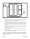
UART TRANSMIT SECTION
The UART transmitters are programmed for the appropriate baud, number of data bits, and whether or
not parity is to be enabled for the output data to be transmitted. This circuit reacts to a “Data Ready”
flag, and latches the data into its 16-byte FIFO. The data is then loaded into the transmitter shift
register, and is then shifted out. The parity is transmitted as received from the T1 receiver, and is not
checked or regenerated. The end equipment is responsible for parity checking.
The NCM module utilizes two additional transmitter circuits that interface with the Common Module
exclusively in NMS mode of operation. These circuits include “Address Passing” and “Character
Pacing”. Typically, the NCM will allow messages meant for the particular node in which it is
physically installed, to pass, and block all others. However, the NCM can be configured to pass “any
address”, or a wide-range of addresses greater than or less than a specified address.
The Common Module is also given permission to talk to the bus in response to a message qualified as
an address match. All other Common Modules in the network will be forced off the bus as a result of
any valid address header but no address match. The most recent addressed Common Module will have
control of the bus until any other Common Module is addressed.
“Character Pacing” is required so that the NCM does not saturate the Common Module port with a
continuous data stream of characters following an address match. This prevents the Common Module
processor from “missing” characters if they are received without idle time between consecutive
characters.
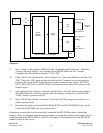
5. T1 TRANSMIT MODULE
The T1 transmit module acknowledges the “Data Ready” flag set by either local UART receivers, and
latches the (character) data. The data is then transmitted in consecutive T1 frames at the proper time
slot on the positive edge of the T1 clock. Indication of T1 transmit can be observed at the TXA and/or
TXB LEDs, and via the NMS software.
If the NCM has both busses enabled, the data received from a T1 bus is re-transmitted back onto the
same bus on the next frame. This pass-thru data has higher priority over the data from the local UART
receivers.
The NCM, for all modes except NMS mode, transmits an idle pattern when data is not active at either
UART receiver, or the T1 bus (if applicable). The idle pattern may be interrupted at any time when
data is ready to be transmitted.
In NMS mode only, the NCM transmits an address pattern when data is not active at either UART
receiver, or the T1 bus (if applicable). The address pattern may be interrupted at any time when data is
ready to be transmitted. The address frames are received and terminated at the adjacent NCM in the
network.