


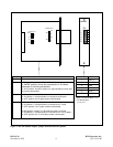
14. Set DIP switches SW6-7 and SW6-8 to set the word length (number of bits per character) in
accordance with Table 1. If the system application mode is NMS, the word length must be set
to the same word length as the local common module. Otherwise, any word length can be used.
NOTE
RFL NCM RFL Electronics Inc.
November 6, 2007 10 (973) 334-3100
In any Application Mode, the Baud Rate, Parity and Word Length settings of the NCM must
match at all nodes in the network. Additionally, In the NMS application mode, the Baud Rate,
Parity and Word Length settings of the NCM and CM must match at all nodes in the network.
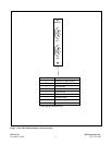
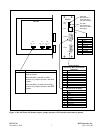
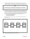
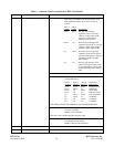
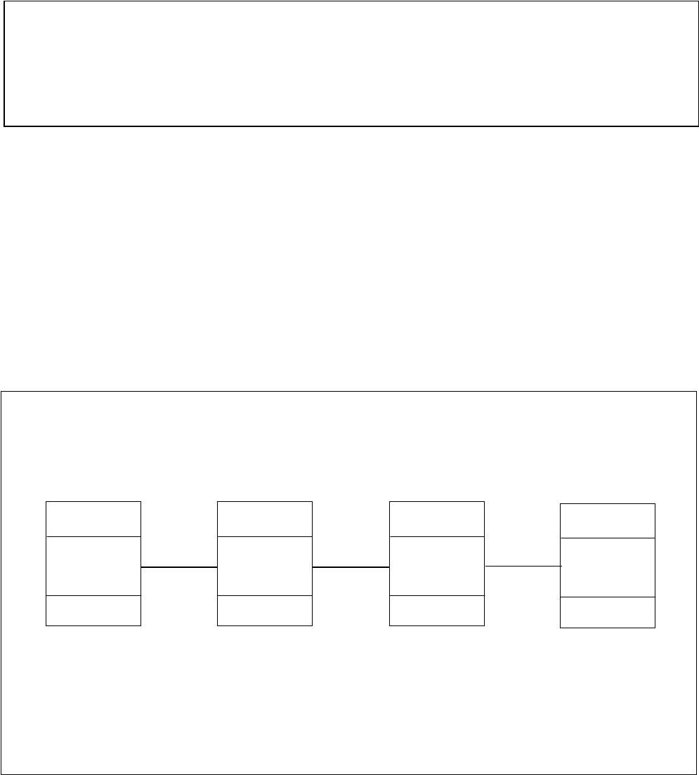
15. Switches SW7-1 and SW7-2 are only used when the NCM module is in the NMS application
mode. In all other application modes these switch settings are ignored. Use DIP switches SW7-
1 and SW7-2 to set the CM address Pass Setting in accordance with Table 1. Typically, if all
the nodes in a T1/E1 network have an NCM as shown in Figure 6, the address Pass Setting will
be set to only pass messages with addresses equal to the local CM address of the NCM. This
feature prevents the local node from responding to queries sent to remote nodes.
Place SW7-1 in the DOWN position
Place SW7-2 in the UP position
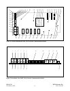
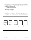
In this example, all inter-node communication is done via the NCM path and FDL (Facility
Data Link) is not used.
IMUX 2000
NCM in NMS mode
(CM address = 1)
(NCM address = 1)
SW7-1 = DOWN
SW7-2 = UP
IMUX 2000
NCM in NMS mode
(CM address = 2)
(NCM address = 2)
SW7-1 = DOWN
SW7-2 = UP
Node 1 Node 2 Node 3 Node 4
IMUX 2000
NCM in NMS mode
(CM address = 4)
(NCM address = 4)
SW7-1 = DOWN
SW7-2 = UP
IMUX 2000
NCM in NMS mode
(CM address = 3)
(NCM address = 3)
SW7-1 = DOWN
SW7-2 = UP
Figure 6. Typical network example with all nodes having an NCM module