


INSTALLATION
Before the RFL NCM module can be placed in service, it must be installed in a multiplexer shelf.
Installation involves determining the module slot in the Main Shelf or Expansion Shelf where the
module will be installed, inserting a Module Adapter into the rear of the shelf behind the module slot,
connecting all signal and power wiring to the Module Adapter, checking the settings of all switches,
and inserting the module into the front of the shelf.
NOTES
Power supply and time slot considerations may affect the installation of this module into an
existing multiplexer shelf. Refer to the multiplexer manual for more information.
The following instructions are provided for installing an RFL NCM module into an existing system. If
the module was included as part of a system, installation was done at the factory. Otherwise, proceed
as follows:
1. Carefully inspect the module for any visible signs of shipping damage. If you suspect damage
to the module, immediately call RFL Customer Service at the number listed at the bottom of
this page.
2. Determine the module slot in the Main Shelf or Expansion Shelf where the module will be
installed.
The RFL NCM module occupies one module slot in the Main Shelf or Expansion
Shelf.
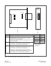
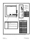
3. Determine which module adapter will be used to make connections to the RFL NCM module.
Each module in the IMUX 2000 multiplexer requires a Module Adapter. The
module adapter provides the appropriate connector for the desired interface.
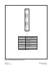
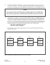
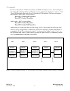
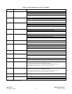
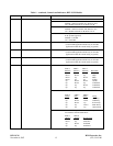
There are three Module Adapters that are compatible with the RFL NCM:
Module Part Number Interface Type Connector Figure
Adapter
MA-402I 9547-16921 2-Port RS-232 9-pin D-subminiature 1
MA-485 107470 1-Port RS-485 Removable terminal block 2
MA-490 107495 2-Port RS-232 9-pin D-subminiature* 3
Telnet I/O 1-ethernet port RJ-45 jack
*One 9-pin connector is the RS-232 port. The other 9-pin connector is the local port.
RFL NCM RFL Electronics Inc.
November 6, 2007 3 (973) 334-3100