


RFL NCM RFL Electronics Inc.
November 6, 2007 24 (973) 334-3100
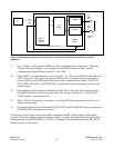
In the Broadcast Mode of operation, all nodes receive the same data regardless of who is transmitting.
The broadcasting applies to both ports of a two-port I/O.
The Master Mode of operation designates a particular NCM at a node, as the master. If the NCM is set
up for TERM/DI-A or DI-B operation, and the I/O has only one port, the actual functionality is the
same as the broadcast mode. If the NCM is set up for both DI-A and DI-B operation, the data received
from either bus is terminated and is not passed back onto the bus. If the I/O has two ports, Port 2 is
always the slave to the Port 1 master, and cannot transmit onto or receive from the T1 bus. Typically,
the master transmits to and receives from all of the slave locations. Only one slave can transmit onto
the T1 bus any time, otherwise the data received by the master will be corrupted.
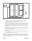
The D&I Slave Mode of operation designates an NCM at a D&I node as slave that must pass data thru
but only transmits to and receives from the master. Set for TERM/DI-A or DI-B operation towards the
master location. Only one slave can transmit onto the T1 bus any time, otherwise the data received will
be corrupted.
The End Slave Mode of operation designates the particular NCM at a node as the terminating point of
a network that is not the master. The NCM is setup for TERM/DI-A or DI-B operation depending on
the direction to be terminated. If the I/O has only one port, the actual functionality is the same as the
broadcast mode. If the I/O has two ports, both ports are slaves that transmit to and receive from the
master, but not with one another.
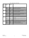
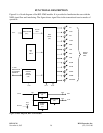
The NMS uses the following I/O Interface types:
I/O Types/Module Adapter
RS-232 (or none)/ MA-402I
Ethernet/ MA-490
RS-485 4W/ MA-485
RS-485 2W/ MA-485
The MA-485 I/O is used for both 2W and 4W RS-485 applications, and will support all of the NCM
Application Modes except NMS mode. The jumper position on the I/O is set to either “2W” or “4W”,
and sets the Type ID accordingly. The input and output serial data is routed as required for the selected
RS-485 type. In “4W” mode, a jumper on the I/O will force the driver to always be enabled so that an
idle condition produces a MARK output. The “2W” mode only supports half-duplex operation, while
the “4W” mode supports both half and full duplex operation.
3. UART RECEIVE SECTION
The UART receivers are programmed for the appropriate baud, number of data bits, and parity for the
input data expected to be received. The input data, including start, stop, and parity, is sampled by a
64X nominal baud internal clock. The received parity bit is compared to the parity calculated by the
UART> Once the data is recognized as valid, the data is latched and is ready for transmission. The
UART receiver is reset if a framing error, parity error, or break indication is detected.