


RFL NCM RFL Electronics Inc.
November 6, 2007 31 (973) 334-3100
LOOP TEST PROCEDURE FOR RFL NCM MODULES IN NMS MODE
INSTALLED IN DI-B CONFIGURED MULTIPLEXERS
The following procedure is used to test RFL NCM modules installed in IMUX 2000, DI-B configured
multiplexers. To test NCM modules installed in IMUX 2000 terminal multiplexers, use the procedure
on page 27 of this instruction data sheet. Before performing this procedure, make sure the system is
on-line and out-of-service.
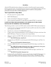
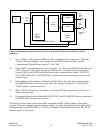
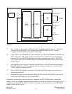
1. Connect the male to female null modem RS-232 cable from CH2 of the MA-401I to the DB9
male connector on the CM I/O.
2. Open the door on the front of the IMUX 2000 multiplexer.
3. Connect a patch cord between the DS1-B EQUIP OUT and DS1-B EQUIP IN jacks on the
front of the IMUX 2000 chassis. The jacks are located on the Common Module.
4. With power applied to the IMUX 2000, check the indicators on the front of the power supply
module.
The POWER indicator should be lit.
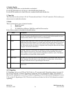
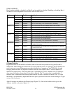
5. Check the Service LED (DS13) on the front panel of the NCM. See Figure 4 and Table 1 for
location.
The Service LED should be illuminated green.
6. Check the ADRA LED (DS11) on the front panel of the NCM. See Figure 4 and Table 1 for
location.
The ADRA LED should be illuminated solid orange. (should not be red or green)
Orange indicates the NCM is receiving its own address.
7. Check the RXA LED (DS7) on the front panel of the NCM. See Figure 4 and Table 1 for
location.
The RXA LED should be illuminated red.
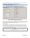
8. Connect the PC to the CH1 RS-232 connector using the male to female RS-232 connector. At
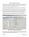
this point, the equipment should be connected as shown in Figure 11. Run the RFL NMS
communications software and set the parameters exactly the same as the CM and the NCM.