RFL NCM RFL Electronics Inc.
November 6, 2007 32 (973) 334-3100
CH1
CH2
PC
IMUX 2000 DROP/INSERT MULTIPLEXER
DS1-B EQUIP OUT
LOOP TEST
CABLE
DS1-B EQUIP IN
DS1-A EQUIP OUT
DS1-A EQUIP IN
CM
DI-B
CM
DI-A
NCM
MODULE
RS232
MA-402I
MODULE
A
DAPTER
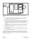
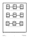
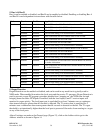
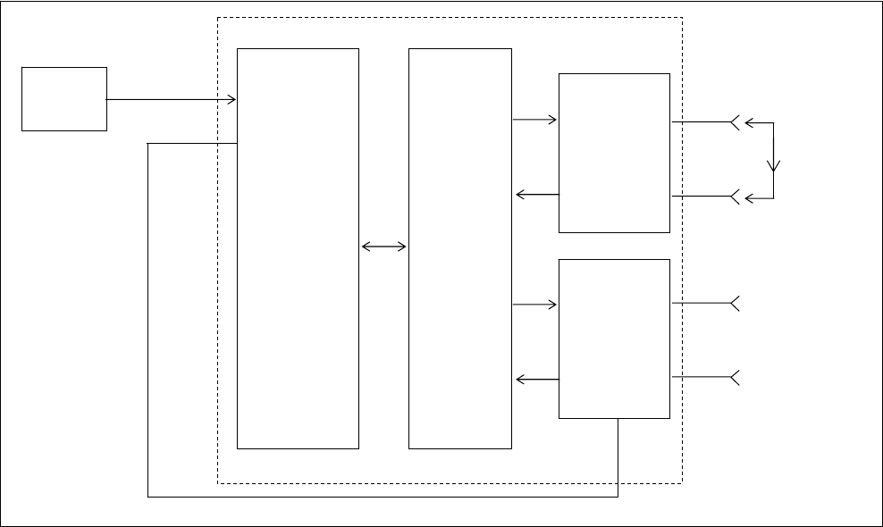
Figure 11. Simplified block diagram, loop test for RFL NCM module in NMS mode, installed in a DI-B configured
multiplexer.
9. Go to “Setup” on the toolbar in NMS, and select “Communication Preferences”. Check the
“Change Advanced Settings” box, and enter the NCM/CM address into the “Assume
Communication Works/Comm to node #”. Click “OK”.
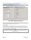
10. Check “Read” Icon and check the “Auto Configure” box. Then select Method 3 and then click
“OK”. Then click “OK” again and proceed with the read. Commands sent to and responses
from the CM (via the NCM) should be evident in the communications window. IN1 (DS1),
OUT2 (DS2), IN2 (DS3), and OUT2 (DS4) will illuminate green when data is present at the
respective port.
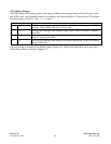
11. Once the Read of the node has concluded, click the NetVw Icon. The node corresponding to
the NCM/CM address should be present. Select this node by clicking on it. Verify that the
“NCM” module is present in the list.
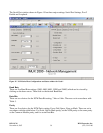
12. Select “NCM” and click the view button. Verify that all NCM settings are correctly set. (i.e.
address passing mode)
13. Disconnect the patch cord from the DS1-B EQUIP OUT and DS1-B EQUIP IN jacks on the
front of the IMUX 2000, and close the front door.
If the above test procedure can be successfully completed, the RFL NCM module is functioning
properly. If not, use standard troubleshooting procedures to isolate the problem to the module itself, to
another module in the IMUX 2000, or to the T1 or E1channel. If the problem lies in the RFL NCM
module, replace it with a spare.


