


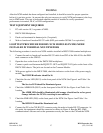

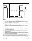
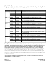
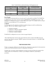
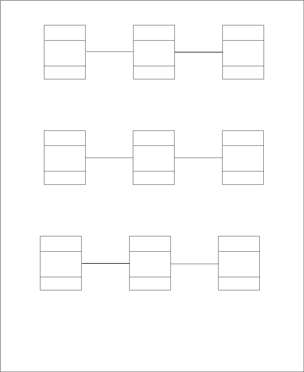
Figure 13a. Typical 3-node network using MA-485s (1 RS-485 port)
IMUX 2000
NCM in
Broadcast mode
MA-485
IMUX 2000
NCM in
Broadcast mode
MA-485
IMUX 2000
NCM in
Broadcast mode
MA-485
Node 1 Node 2 Node 3
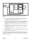
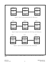
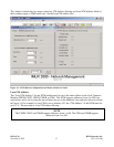
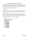
Figure 13b. Typical 3-node network using MA-490s (1 RS-232 port, and 1 Ethernet port)
IMUX 2000
NCM in
NMS mode
MA-490
IMUX 2000
NCM in
NMS mode
MA-490
IMUX 2000
NCM in
NMS mode
MA-490
Node 1 Node 2 Node 3
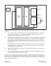
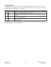
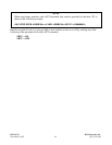
Figure 13c. Typical 3-node network using MA-402Is (2 RS-232 ports)
IMUX 2000
NCM in
Master mode
MA-402I
IMUX 2000
NCM in
D&I Slave mode
MA-402I
IMUX 2000
NCM in
End Slave mode
MA-402I
Node 1 Node 2 Node 3
Figure 13. Typical networks showing NCM module configured as Master, D&I Slave, End Slave, Broadcast and
NMS.
RFL NCM RFL Electronics Inc.
November 6, 2007 35 (973) 334-3100