


RFL NCM RFL Electronics Inc.
November 6, 2007 23 (973) 334-3100
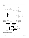
1. SCB MODULE
The SCB circuit is used to generate the read, write, and address data necessary to transfer control and
status data to and from the SCB bus. The SCB address is configured externally via SW1 and is
selectable between 1 and 36. The SCB circuit also communicates to the Common Module the
following information: Card Type (117), number of configuration bytes, and number of status bytes.
In LOCAL mode the position of configuration switches (SW1 through SW9) are “read” by the
Common Module, and then converted into standard P code and S code format.
In REMOTE mode, the NCM module does not rely on the position of configuration switches (SW2
through SW9). Instead, the Common Module “writes” the configuration to the NCM. The NCM
requires that it receives exactly the same information three consecutive times before it accepts the
updated configuration information as correct.
NCM “Service” is qualified in order to minimize user setup error, and prevents operation if the quality
of the bus signal prevents the logic from determining whether the multiplexer is T1 or E1. In general,
E1 does not allow the use of TS0 and TS16 if CAS is enabled, and T1 does not allow the setting of
TS0 or any setting greater than TS24. It is the users responsibility to be aware of the network setup
before selecting a channel to use. This qualification does not detect or prevent “stepping” on a time
slot previously in use, including those that may be used for Fast Reframing, or network
communications (NMX in E1). NCM “Service” is also qualified for non-existent and invalid modes of
operation.
2. APPLICATION MODES AND INTERFACES
NCM operation depends on the selected Application Mode, and the type of I/O interface installed. The
NCM uses an I/O type ID to determine which I/O is installed. If the installed I/O is the MA-485, an
additional bit is used to indicate whether it includes one or two ports. The two port version does not
currently exist.
The NMS includes the following Application Mode settings, and I/O types
Application Mode settings
NMS Mode
Broadcast Mode
Master Mode
D&I Slave Mode
End Slave Mode
The purpose of the NMS Mode is to provide a high-speed communication path between nodes for
NMS. The other application modes provide a communication path between an MTU and several
RTUs. The NMS Mode of operation requires the use of the MA-402I with two RS-232 ports, or the
MA-490 with two RS-232 ports and an Ethernet port. In respect to the NCM, Port 1 is the “Local” port
and Port 2 is the “CM” port. The additional RS-232 port on the MA-490 is used to configure the local
Ethernet Port. The NMS mode is a Broadcast-type application but includes “Address Passing” and
“Character Pacing” circuits for the “CM” port.