


RFL NCM RFL Electronics Inc.
November 6, 2007 13 (973) 334-3100
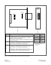
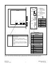
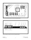
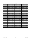
Table 1. - continued, Controls and indicators, RFL NCM Module
Item Name/Description Function
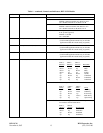
15 DIP Switch, SW2 SW2-1 to SW2-5 Selects Time Slot (See Table 4)
SW2-6 Selects Transmit on A Receive on B
DOWN = enables Transmit on A, Receive on B
UP = disables Transmit on A, Receive on B
SW2-7 Selects transmit on B receive on A
DOWN = enables Transmit on B, Receive on A
UP = disables Transmit on B, Receive on A
SW2-8 In E1 Systems, Selects CAS ON or OFF
In T1 Systems (ignored)
DOWN = CAS ON
UP = CAS OFF
16 Rotary Switch, SW3 (Hundreds) SW3-1 to SW3-10 Selects Hundreds position of “Local CM Address”
(Used in NMS application mode only. In all other
application modes this switch setting is ignored.)
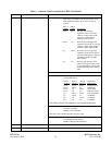
17 Rotary Switch, SW4 (Tens) SW4-1 to SW4-10 Selects Tens position of “Local CM Address”
(Used in NMS application mode only. In all other
application modes this switch setting is ignored.)
18 Rotary Switch, SW5 (Units) SW5-1 to SW5-10 Selects Units position of “Local CM Address”
(Used in NMS application mode only. In all other
application modes this switch setting is ignored.)
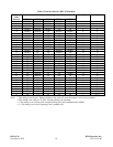
19 DIP Switch, SW6 SW6-1 to SW6-3 Selects Baud Rate in accordance with the table below:
SW6-1 SW6-2 SW6-3
(Baud 2) (Baud 1) (Baud 0) Baud Rate
Down Down Down 2400
Down Down Up 4800
Down Up Down 9600
Down Up Up 19,200
Up Down Down 38,400
Up Down Up Undefined
Up Up Down Undefined
Up Up Up Undefined
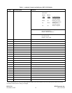
SW6-4 to SW6-6 Selects Parity in accordance with the table below:
SW6-4 SW6-5 SW6-6
(PEN) (SP) (EPS) Parity
Down Down Down No Parity
Up Down Down Odd Parity
Up Down Up Even Parity
Up Up Down Mark Parity
Up Up Up Space Parity
SW6-7 to SW6-8 Selects Word Length (Number of data bits per character)
in accordance with the table below:
SW6-7 SW6-8
(WLS1)
(WLS0) Word Length
Down Down 7 data bits
Down Up 8 data bits
Up Down undefined
Up Up undefined