


The Address window has two major selections, CM Address Passing and Local CM Address. Both of
these settings apply to NMS mode only. Set the local CM address first.
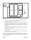
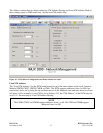
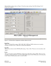
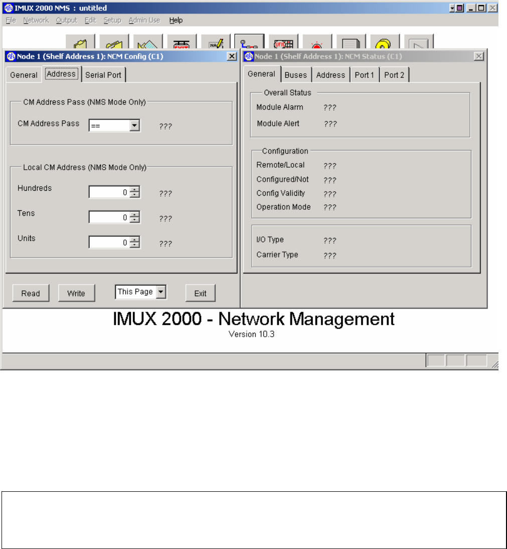
Figure 14. NCM Address Configurations and Status window for Node 1
Local CM Address
The “Local CM Address” for the NCM module must be set to the same address as the local Common
Module (CM3B, CM3C, CM3R, CM6B, or CM4). The NCM supports addresses from 1 to 999 (see
note below) and is set by using the up and down arrows in the hundreds, tens and units boxes as shown
in Figure 14. For example, if your CM4 is set to Address 351, the “CM Address” of the NCM must be
set to 351. The next step is to set CM Address Passing.
NOTE
The CM3B, CM3C and CM6B support addresses from 1 to 99. The CM4 and CM6B support
addresses from 1 to 500.
RFL NCM RFL Electronics Inc.
November 6, 2007 37 (973) 334-3100