


RFL NCM RFL Electronics Inc.
November 6, 2007 12 (973) 334-3100
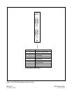
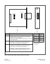
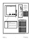
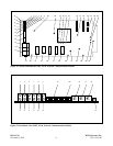
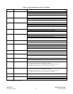
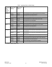
Table 1. Controls and indicators, RFL NCM Module
Item Name/Description Function
1 IN1 LED DS1 Lights (GREEN) when Port 1 Input Data is active and no errors detected
Lights (RED) when Port 1 Input Data is active and errors are detected
Lights (flashing RED) when Port 1 Rogue detector is active
LED is (OFF) when Port 1 Input Data is idle
2 OUT1 LED DS2 Lights (GREEN) when Port 1 Output Data is active and no errors detected
Lights (RED) when Port 1 Output Data is active and errors are detected
LED is (OFF) when Port 1 Output Data is idle
3 IN2 LED DS3 Lights (GREEN) when Port 2 Input Data is active and no errors detected
Lights (RED) when Port 2 Input Data is active and errors are detected
Lights (flashing RED) when Port 2 Rogue detector is active
LED is (OFF) when Port 2 Input Data is idle
4 OUT2 LED DS4 Lights (GREEN) when Port 2 Output Data is active and no errors detected
Lights (RED) when Port 2 Output Data is active and errors are detected
LED is (OFF) when Port 2 Output Data is idle
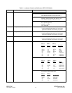
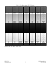
5 RXB LED DS5 Lights (GREEN) when T1/E1 Receive Data from BUS B is active and no errors detected
Lights (RED) when T1/E1 Receive Data from BUS B is active and errors are detected
Lights (flashing RED) when Receive BUS B Rogue detector is active
LED is (OFF) when T1/E1 Receive Data from BUS B is idle
6 TXA LED DS6 Lights (GREEN) when T1/E1 Transmit Data to BUS A is active
LED is (OFF) when T1/E1 Transmit Data to BUS A is idle
7 RXA LED DS7 Lights (GREEN) when T1/E1 Receive Data from BUS A is active and no errors detected
Lights (RED) when T1/E1 Receive Data from BUS A is active and errors are detected
Lights (flashing RED) when Receive BUS A Rogue detector is active
LED is (OFF) when T1/E1 Receive Data from BUS A is idle
8 TXB LED DS8 Lights (GREEN) when T1/E1 Transmit Data to BUS B is active
LED is (OFF) when T1/E1 Transmit Data to BUS B is idle
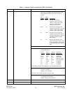
9 EQLB LED DS9 Lights (YELLOW) when Equipment Loopback for ports 1 and 2 is active
LED is OFF when Equipment Loopback for ports 1 and 2 is inactive
10 PALB LED DS10 Lights (YELLOW) when Payload Loopback for ports 1 or 2 is active
LED is OFF when Payload Loopback for ports 1 and 2 is inactive
11* ADRA LED DS11 Lights (GREEN) when NCM is receiving any CM address except its own from Bus A.
(This will occur during T1/E1 Line and Payload Loopbacks)
Lights (YELLOW) when NCM is receiving only its own CM address from Bus A.
Lights (RED) when NCM is not receiving any CM address from Bus A.
12* ADRB LED DS12 Lights (GREEN) when NCM is receiving any CM address except its own from Bus B.
(This will occur during T1/E1 Line and Payload Loopbacks)
Lights (YELLOW) when NCM is receiving only its own CM address from Bus B.
Lights (RED) when NCM is not receiving any CM address from Bus B.
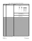
13 Service ON LED DS13 Lights (GREEN) when service is ON
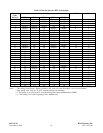
14 DIP Switch, SW1 SW1-1 to SW1-6 Selects SCB Address (See Table 3)
SW1-7 For RFL use
SW1-8 For RFL use
*Used in NMS application mode only.