


RFL NCM RFL Electronics Inc.
November 6, 2007 41 (973) 334-3100
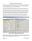
REMOTE CONTROL USING SCL COMMANDS
When installed in an IMUX 2000 remote controllable shelf, the NCM module can be operated under
local or remote control. When under remote control, certain configuration parameters can only be
changed through the RS-232 remote port on the multiplexer. The remote interface for this module
involves two codes: a “P” (parameter) code, and an “S” (status) code. See the IMUX 2000 instruction
manual for more information on the remote control interface.
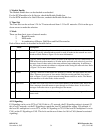
The NCM module reports itself as a “Type 117” module.
“P” CODES
“P” codes, when used in the parameter field on a “SET” command, allow the user to set certain
parameters on the module by remote control, just like setting the switches on a module under local
control. “P” codes also appear in the response to a “CONFIG?” query, showing the current parameter
settings on the module.
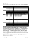
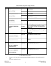
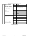
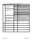
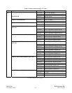
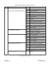
There are ten “P” codes for the NCM module: P01 through P10. Each of these P codes can be a
decimal number from 0 to 255, which can also be represented as an eight-digit binary number (in
parenthesis). The binary representation is more useful for setting and interpreting the “P” codes, since
each binary digit (0 or 1) corresponds to the ON or OFF setting for a particular switch on the module.
Table 6 describes the meanings of the “P” codes for the NCM module.
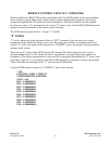
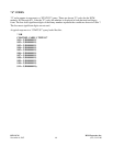
A typical NCM module response to a “CONFIG?” query looks like this:
* OK
CHANNEL CARD 3, TYPE 117
UNDER REMOTE CONTROL
SVCE = ON
P01 = 3 (B00000011)
P02 = 1 (B00000001)
P03 = 1 (B00000001)
P04 = 1 (B00000001)
P05 = 1 (B00000001)
P06 = 1 (B00000001)
P07 = 1 (B00000001)
P08 = 1 (B00000001)
P09 = 1 (B00000001)
P10 = 1 (B00000001);