Section 27 Video Display Controller 3
R01UH0134EJ0400 Rev. 4.00 Page 1615 of 2108
Sep 24, 2014
SH7262 Group, SH7264 Group
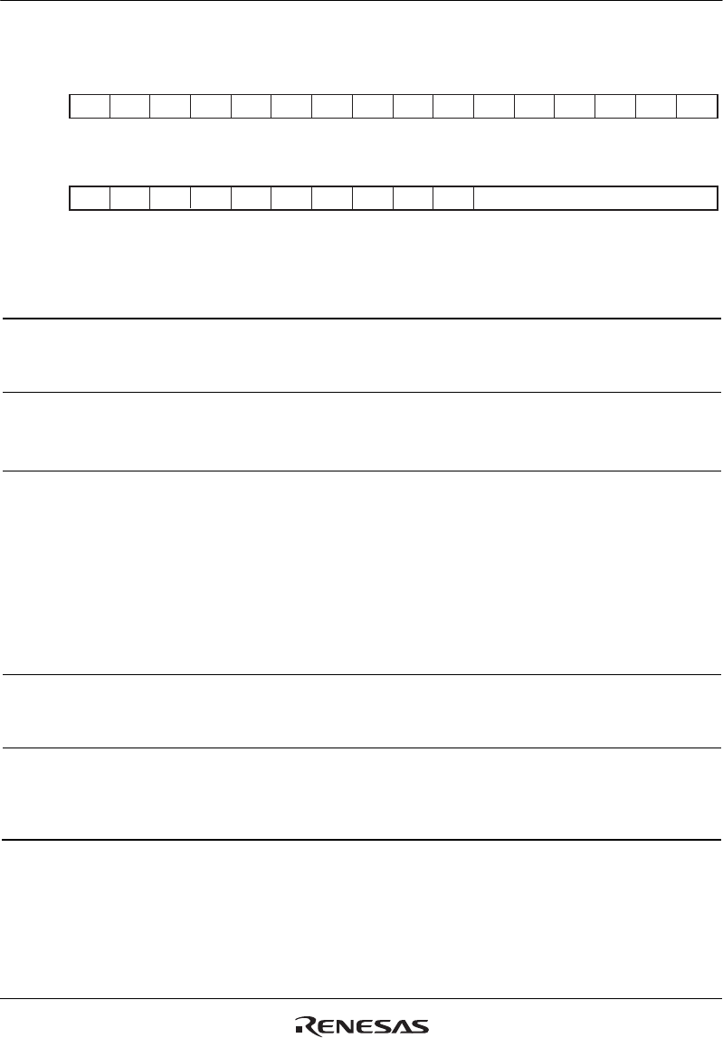
27.7.32 Panel Clock Select Register (PANEL_CLKSEL)
31 30 29 28 27 26 25 24 23 22 21 20 19 18 17 16
15 14 13 12 11 10 9 8 7 6 5 4 3 2 1
0
0000000000000000
RRRRRRRRRRRRRRRR
0000000000000001
R R R/W R/W R R R R R R R/W R/W R/W R/W R/W R/W
------
-
----------
- - ICKSEL ICKEN - ---- DCDR[5:0]
Bit:
Initial value:
R/W:
Bit:
Initial value:
R/W:
Bit Bit Name
Initial
Value R/W Description
31 to 14 All 0 R Reserved
These bits are always read as 0. The write value
should always be 0.
13 ICKSEL 0 R/W Selects the source of the panel clock.
0: External clock is selected (LCD_EXTCLK).
1: Bus clock is selected (B).
12 ICKEN 0 R/W Enables or disables the operation of the blocks
using the panel clock in this module and output of
the panel clock.
0: Operation of the blocks using the panel clock is
disabled.
1: Operation of the blocks using the panel clock is
enabled.
Note: Be sure to clear this bit to 0 before modifying
the ICKSEL or DCDR bit.
11 to 6 All 0 R Reserved
These bits are always read as 0. The write value
should always be 0.
5 to 0 DCDR[5:0] 000001 R/W Specifies the division ratio of the input clock
frequency. For details, see table 27.14.
Note: The settings not shown in table 27.14 are
prohibited.
This module can select the bus clock or external clock as the source of the panel clock. It also has
a frequency divider providing a division ratio from 1/1 to 1/32.


