


11 - 20 11 - 20
MELSOFT
11. POSITIONING DEBUGGING
DISPLAY/SETTING SCREE
N
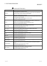
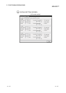
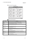
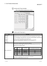
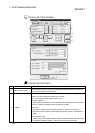
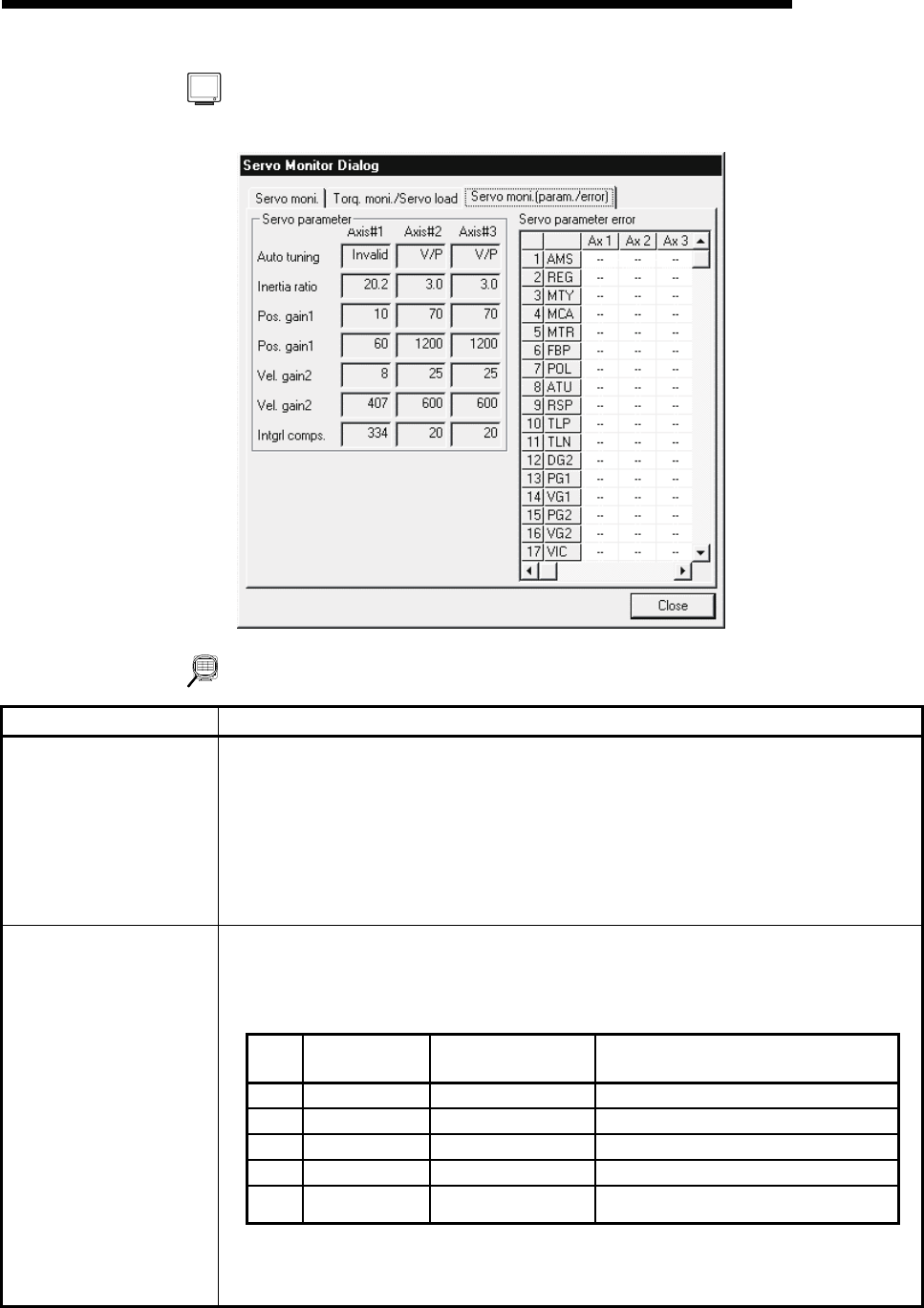
[Servo parameter/Servo parameter error monitor]
DISPLAY/SETTING DATA
Item Description
Auto tuning
Inertia ratio
Pos. gain 1
Pos. gain 2
Vel. gain 1
Vel. gain 2
Intgrl comps.
Indicates the type of auto tuning selected in the servo basic parameters (refer to Section
8.2.1) and the settings of load inertia ratio, control gains and speed integral compensation set
to the servo extension parameters (refer to Section 8.2.2).
When auto tuning is executed, the settings of the auto tuning are displayed.
Buffer memory address (Axis #1): 108, 112, 113, 114, 115, 116, 117
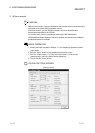
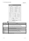
Shows the servo parameter types and their error definitions.
No. represents the lower 2 digits of the buffer memory address where the Axis #1 servo
parameters of the AD75M are stored.
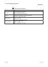
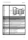
No. Abbreviation Servo Parameter
Buffer Memory Address where AD75M
Servo Parameter Is Stored (Axis #1)
1 AMS Amplifier set 101
2 REG Regenerative 102
3 MTY Motor type 103
4 MCA Motor capacity 104
.
.
.
.
.
.
.
.
.
.
.
.
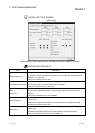
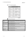
Servo parameter error
Error definition is displayed per servo parameter item of each axis.
Buffer memory address (Axis #1): 870, 871, 872