Section 11 Multi-Function Timer Pulse Unit 2
Page 564 of 2108 R01UH0134EJ0400 Rev. 4.00
Sep 24, 2014
SH7262 Group, SH7264 Group
Example of Procedure for Setting Output Waveform Control at Synchronous Counter Clearing
in Complementary PWM Mode
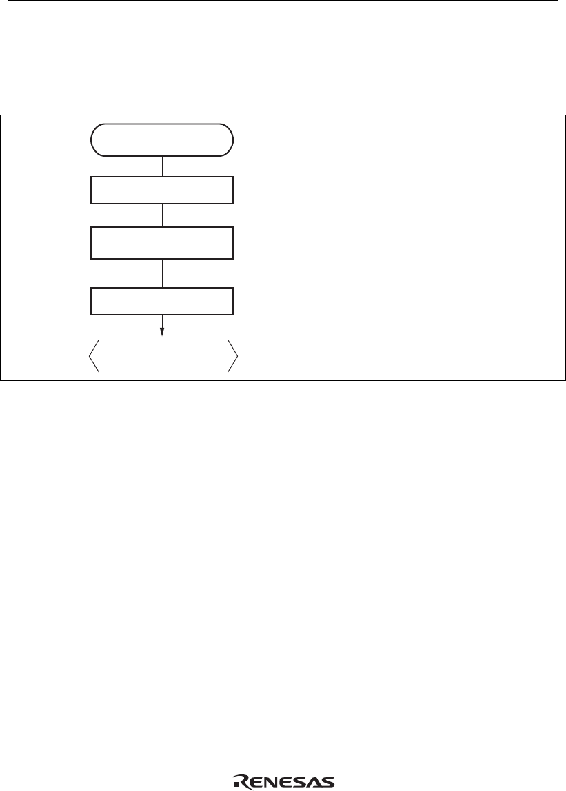
An example of the procedure for setting output waveform control at synchronous counter
clearing in complementary PWM mode is shown in figure 11.57.
Stop count operation
Output waveform control at
synchronous counter clearing
Set TWCR and
complementary PWM mode
Start count operation
Output waveform control at
synchronous counter clearing
[1]
[2]
[3]
[1] Clear bits CST3 and CST4 in the timer
start register (TSTR) to 0, and halt timer
counter (TCNT) operation. Perform
TWCR setting while TCNT_3 and
TCNT_4 are stopped.
[2] Read bit WRE in TWCR and then write 1
to it to suppress initial value output at
counter clearing.
[3] Set bits CST3 and CST4 in TSTR to 1 to
start count operation.
Figure 11.57 Example of Procedure for Setting Output Waveform Control at Synchronous
Counter Clearing in Complementary PWM Mode


