Section 20 Controller Area Network
R01UH0134EJ0400 Rev. 4.00 Page 1057 of 2108
Sep 24, 2014
SH7262 Group, SH7264 Group
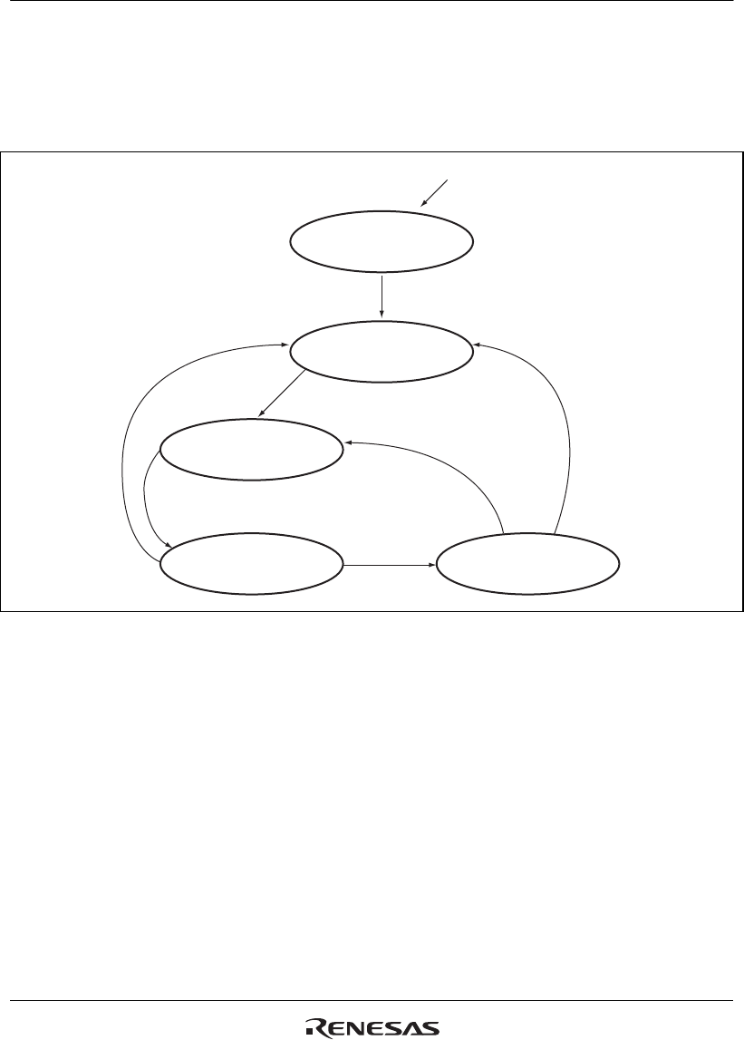
Figure 20.15 shows allowed state transitions.
Please don't set MCR5 (Sleep Mode) without entering Halt Mode.
After MCR1 is set, please don't clear it before GSR4 is set and this module enters Halt
Mode.
Power On/SW Reset
Reset
clear MCR0
and GSR3 = 0
clear MCR1
and MCR5
Transmission
Reception
set MCR1*
3
Halt Request
except Transmitter/Receiver/BusOff, if MCR6 = 0
BusOff or except Transmitter/Receiver, if MCR6 = 1
Halt Mode
clear MCR5*
1
clear MCR5
set MCR1*
4
Sleep Mode
set MCR5
clear MCR1*
2
Figure 20.15 Halt Mode/Sleep Mode
Notes: 1. MCR5 can be cleared by automatically by detecting a dominant bit on the CAN Bus if
MCR7 is set or by writing '0'.
2. MCR1 is cleared in SW. Clearing MCR1 and setting MCR5 have to be carried out by
the same instruction.
3. MCR1 must not be cleared in SW, before GSR4 is set. MCR1 can be set automatically
in HW when this module moves to Bus Off and MCR14 and MCR6 are both set.
4. When MCR5 is cleared and MCR1 is set at the same time, this module moves to Halt
Request. Right after that, it moves to Halt Mode with no reception/transmission.
The following table shows conditions to access registers.


