


Index
MN1921
J
Jumper settings
CAN terminator, 4-18
error output, 4-14
L
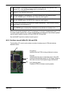
LED indicators
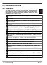
status display, 6-2
surface mount, 6-3
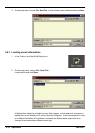
Loading saved information, 5-12
O
Operation, 5-1
connecting to the PC, 5-1
installing WorkBench v5, 5-1
power on checks, 5-2
preliminary checks, 5-1
starting, 5-1
P
Power
sources, 3-3, 4-3, 7-1
using a single drive supply, 4-3
using separate drive and logic supplies, 4-4
Precautions, 1-2
R
Receiving and Inspection, 2-2
RELAY keyword, 4-14
RS232 port, 4-15
S
Safety Notice, 1-2
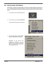
Saving setup information, 5-11
Scale, selecting, 5-6
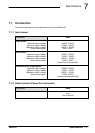
Specifications, 7-1
analog inputs, 7-2
analog outputs, 7-2
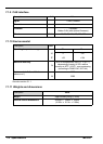
CAN interface, 7-4
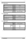
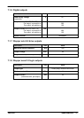
digital inputs, 7-2
digital outputs, 7-3
environmental, 7-4
input power, 7-1
output power, 7-1
stepper axis outputs, 7-3
stepper logic outputs, 7-3
weights and dimensions, 7-4
Status display, 6-2
Stepper axis, 5-8
0-2 drive outputs, 4-5
connecting a 4-wire motor, 4-5
connecting a 6-wire motor, 4-6
connecting a 8-wire motor, 4-7
0-3 logic outputs, 4-8
testing the output, 5-8
T
Testing, an axis, 5-8
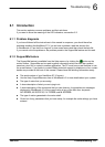
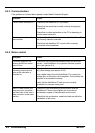
Troubleshooting, 6-1
communication, 6-4
help file, 5-3
motor control, 6-4
problem diagnosis, 6-1
status display, 6-2
SupportMe, 6-1
U
Units and abbreviations, 2-3
W
Weights and dimensions, 7-4
WorkBench v5, 5-3
digital input/output configuration, 5-9
help file, 5-3
loading saved information, 5-12
saving setup information, 5-11
starting, 5-4