


Input / Output 4-17MN1921
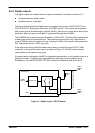
4.6.3 CAN communication
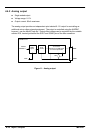
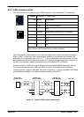
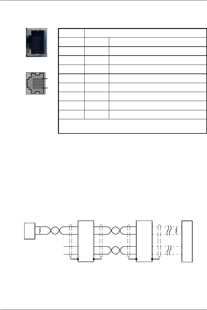
The CAN connection is made using the RJ45 connector on the NextMove ST control card.
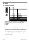
Location
NextMove ST control card
Pin Name Description
1 CAN+ CAN channel positive
2 CAN - CAN channel negative
3 - (NC)
4 CAN 0V Ground/earth reference for CAN signals
5 CAN V+ CAN power V+ (12-24V)
6 - (NC)
7 - (NC)
8 - (NC)
Description
Opto-isolated CAN interface using a RJ45 connector.
CAN offers serial communications over a two wire twisted pair cable up to maximum length of
500m (1640ft). It offers very high communication reliability in an industrial environment; the
probability of an undetected error is 4.7x10
-11
. CAN is optimized for the transmission of small
data packets and therefore offers fast update of I/O devices (peripheral devices) connected to
the bus. The maximum (default) transmission rate on NextMove ST is 500Kbit/s.
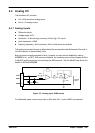
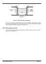
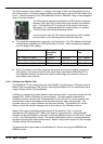
Correct operation of CAN can only be achieved with screened/shielded twisted-pair cabling.
For improved noise immunity, CAN+ and CAN- must form a twisted pair with the shield
connected to the connector backshell, as shown in Figure 16. A range of suitable CAN cables
are available from Baldor, with catalog numbers beginning CBL004-5...
1
2
4
5
NextMoveS T
RJ45 connector
7
2
Baldor HMI
Operator P anel
Twisted pair Twisted pairs
T
R
T
R
End node
1
2
4
5
1
2
4
524V
0V
NextMoveS T
RJ45 connector
Figure 16 - Typical CAN network connections
1
8