


ii Contents
MN1921
5 Operation 5-1..........................................
5.1 Introduction 5-1............................................
5.1.1 Connecting the NextMove ST to the PC 5-1............................
5.1.2 Installing WorkBench v5 5-1.........................................
5.1.3 Starting the NextMove ST 5-1.......................................
5.1.4 Preliminary checks 5-1.............................................
5.1.5 Power on checks 5-2...............................................
5.2 WorkBench v5 5-3..........................................
5.2.1 Help file 5-3......................................................
5.2.2 Starting WorkBench v5 5-4..........................................
5.3 Configuring a n axis 5-6.....................................
5.3.1 Selecting a scale 5-6...............................................
5.4 Stepper axis - testing 5-8....................................
5.4.1 Testing the output 5-8..............................................
5.5 Digital input/output configuration 5-9..........................
5.5.1 Digital input configuration 5-9........................................
5.5.2 Digital output configuration 5-10.......................................
5.6 Saving setup information 5-11.................................
5.6.1 Loading saved information 5-12.......................................
6 Troubleshooting 6-1....................................
6.1 Introduction 6-1............................................
6.1.1 Problem diagnosis 6-1..............................................
6.1.2 SupportMe feature 6-1.............................................
6.2 NextMove ST indicators 6-2.................................
6.2.1 Status display 6-2.................................................
6.2.2 Surface mount LEDs D3, D4 and D16 6-3.............................
6.2.3 Communication 6-4................................................
6.2.4 Motor control 6-4..................................................
7 Specifications 7-1......................................
7.1 Introduction 7-1............................................
7.1.1 Input power 7-1...................................................
7.1.2 Output power (Power Out connector) 7-1..............................
7.1.3 Analog inputs 7-2..................................................
7.1.4 Analog output 7-2..................................................
7.1.5 Digital inputs 7-2..................................................
7.1.6 Digital outputs 7-3.................................................
7.1.7 Stepper axis 0-2 drive outputs 7-3....................................
7.1.8 Stepper axes 0-3 logic outputs 7-3...................................
7.1.9 CAN interface 7-4.................................................
7.1.10 Environmental 7-4.................................................
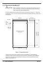
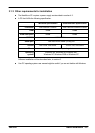
7.1.11 Weights and dimensions 7-4........................................