


4-8 Input / Output MN1921
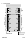
4.3.2 Stepper axes 0-3 logic outputs
J3
DIR3
BOOST3
DIR2
BOOST2
DIR1
BOOST1
DIR0
BOOST0
DGND
STEP3
DGND
STEP2
DGND
STEP1
DGND
STEP0
NextMoveST
STEP0
DGND
ULN2003
Step
Output
74AHCT244
GND
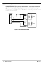
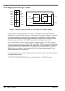
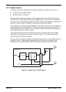
Figure 9 - Stepper output pin heade r J3, and output circuit (STEP0 shown)
To allow external stepper amplifiers to be used, all of the stepper output signals from the
NextMove ST control card are output on a 16-pin header, J3, mounted on the card. There are
four sets of stepper motor control outputs, operating in the range 10Hz to 1MHz. The step
(pulse), direction and boost signals from the NextMove ST control card are divided into two
groups, each group driven by an ULN2003 open collector Darlington output device.
Each ULN2003 has a maximum power dissipation of 900mW at 25°C. The total combined
output requirements for the group DIR0 - DIR2 and STEP0 - STEP2 must not exceed this limit.
The total combined output requirements of the group DIR3, STEP3 and BOOST0 - BOOST3
must not exceed this limit. The maximum current limit for any individual output in a group is
400mA if only one output is in use, reducing to 50mA if all outputs in the group are in use.
These limits are for a 100% duty cycle.
It is recommended to use separate shielded cables for the step outputs. The shield should be
connected at one end only.
The STEP2, DIR2 and BOOST2 outputs are also duplicated on the MISC connector .