


Input / Output 4-11MN1921
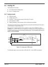
4.5 Digital I/O
The NextMove ST provides:
H 24 general purpose digital inputs.
H 16 general purpose digital outputs.
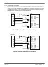
Note: It is recommended to use separate shielded cables for the digital inputs. The
shield should be connected to the input connector’s shield pin.
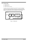
4.5.1 Digital inputs
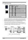
The digital inputs are available across a range of connectors, as shown in section 4.1.1.
All digital inputs have a common specification:
H General purpose 5V TTL digital inputs with internal pull-up resistors. Can also be assigned
to special purposes such as Home, Limit, Stop and Error inputs.
H Sampling frequency: 1kHz
DGND
DIN0
GND
MintMT
INX.0
+5V
NextMoveST
10k
74AHCT14
1nF
3
2
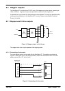
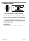
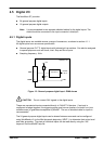
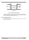
Figure 12 - General purpose digital input - DIN0 shown
CAUTION: Do not connect 24V signals to the digital inputs.
These are unprotected inputs connected directly to 74AHCT14 devices. If an input is
configured as edge triggered, the triggering pulse must have a duration of at least 1ms (one
software scan) to guarantee acceptance by MintMT. The use of shielded cable for inputs is
recommended.
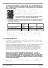
The 24 general purpose digital inputs can be shared between axes and can be configured
using W orkBench v5 (or the Mint keywords beginning INPUT...) to determine their active level
and other properties. The state of individual inputs can be read directly using the INX
keyword. See the MintMT help file.