


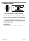

4-12 Input / Output MN1921
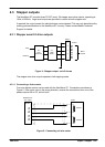
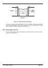
Using a digital input as a LIMIT or HOME input
An input can be configured as a Limit or Home input for any axis, using the
LIMITFORWARDINPUT, LIMITREVERSEINPUT or HOMEINPUT keywords. Typically, limit and
home inputs will be grounded by normally closed switches. When a limit or home switch is
activated, the switch will become open-circuit. If two or more limit switches are to be used they
can be connected in series. If it is necessary to determine which limit has been reached, a
double pole switch can be used at one limit to trigger an additional general purpose digital
input.
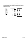
Using a digital input as a STOP input
An input can be configured as a Stop input for any axis, using the STOPINPUT keyword.
Typically , a stop input will be grounded by a normally closed switch. When a stop switch is
activated, the switch will become open-circuit. The action of a STOP input can be controlled
using the STOPINPUTMODE keyword. T ypically, it is used as a safety interlock to stop all axes.
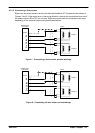
Using a digital input as an ERROR input
An input can be configured as an Error input for any axis, using the ERRORINPUT keyword.
This input can be used to stop the NextMove ST in the event of an error occurring elsewhere
in the system. The action of an ERROR input can be controlled using the ERRORSWITCH and
ERRORINPUTMODE keywords.
See the MintMT help file for details of each keyword.
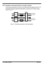
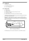
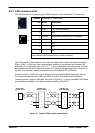
4.5.1.1 Auxiliary Encode r inputs - AUXSTEP IN, AUXDIR IN, AUXZ IN
These inputs accept step (pulse) and direction signals, allowing an external source to provide
the reference for the speed and direction of an axis. The step frequency (20MHz maximum)
determines the speed, and the direction input determines the direction of motion. Both the
rising and falling edges of the AUXSTEP IN input cause an internal counter to be changed. If
5V is applied to the AUXDIR IN input (or it is left unconnected) the counter will increment. If
the direction input is grounded the counter will be decremented.
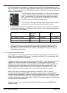
Typically , one channel of an encoder signal (either A or B) would be used to provide the
AUXSTEP IN signal, allowing the input to be used as an auxiliary (master) encoder input. The
input can be used as a master position reference for cam, fly and follow move types. For this,
the MASTERSOURCE keyword must be used to configure the pulse input as a master (auxiliary)
encoder input. The master position reference can then be read using the AUXENCODER
keyword.
Since a secondary encoder channel is not used, the AUXDIR IN input allows the direction of
motion to be determined. The AUXZ IN input can be supplied from the encoder’s index signal,
and may be read using the AUXENCODERZLATCH keyword.
See the MintMT help file for details of each keyword.
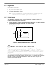
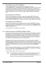
Note: The AUXSTEP IN and AUXDIR IN inputs use the same type of input circuitry as
the other digital inputs (see Figure 12). However, due to the faster internal
processing required for these signals, they are particularly sensitive to noise. For
this reason, connections must use shielded twisted pair cable.