


Input / Output 4-3MN1921
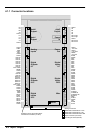
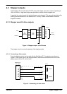
4.2 Power connectio n s
The NextMove ST can accept AC or DC power supplies, and has connections for separate
drive and logic supplies. However, the NextMove ST can operate from a single combined
supply if necessary .
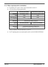
Supply
connection
Recommended
supply volt age
Supply voltage
range
Power
requirement
Logic 24VDC 12-35VDC 60W
24VAC 12- 30VAC 60VA
Drive 24VDC 12-35VDC
(must not exceed 6A)
150W
24VAC 12- 30VAC
(must not exceed 6A RMS)
150VA
Combined
drive and logic
24VDC 12-35VDC
(must not exceed 8.5A)
210W
24VAC 12- 30VAC
(must not exceed 8.5A RMS)
210VA
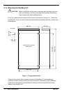
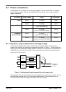
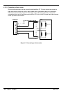
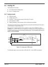
4.2.1 Operation using combined drive and logic supply
To operate the NextMove ST using a combined drive and logic supply, it is necessary to
connect links between the power input connections as shown in Figure 2. The drive and logic
supply inputs have independent bridge rectifiers so polarity is not important. The NextMove ST
creates its own ±12V and +5V supplies for the control card and internal circuitry by deriving
power from the drive supply.
Rectifier
(logic)
Fuse
Fuse
PSU Drive:
12-35VDC or
12-30VAC
POWERIN
5
4
3
2
1
Rectifier
(drive)
Figure 2 - Linking supply inputs to operate from drive supply only
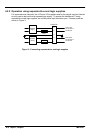
The regulated ±12V and +5V supplies are made available on the power out connector, for use
with low power external circuitry, such as input potentiometers. Current demand must not
exceed 10mA from the ±12V supply and 200mA from the 5V supply.